1. Introduction
The Daylight Analysis Wizard can be used to perform the following calculations: Annual Probable Sunlight Hours, Average Daylight Factors, Daylight Distribution, Equivalent First Zone, Permanent Overshadowing and Vertical Sky Component.
This guide aims to explain how to setup and use the wizard, along with discussing the calculations and outputs from the wizard. The first section of the guide acts as an introduction, and will explain where to find the wizard, along with explaining the setup work that needs to be done before using the wizard. The second section of the guide explains the purpose of each page of the wizard, detailing how to setup the calculations and apply tags to relevant spaces. The third section talks about the CSV files outputted from the wizard, and breaks down what each field means. Finally the last section explains how each calculation is calculated in Tas.
1.1 Before Using the Daylight Analysis Wizard
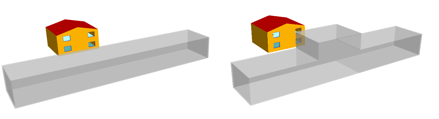
Before using the Daylight Analysis Wizard, you will need to create two t3d files. Both models should contain the building and areas you wish to analyse; however the first model, referred to as the existing model, should also include the surrounding buildings as they currently are. The second model, referred to as the proposed model, should reflect the changes to the surrounding buildings. As the calculations can be performed on the subject building and surrounding buildings, any areas that you wish to compare must have the same zone name and floor area in the existing and proposed buildings.
It is a fundamental requirement that both the existing and proposed t3d files can produce an analysis view without any errors, as a daylight analysis cannot be undertaken on a model with errors.
Please note that if you wish to carry out a Permanent Overshadowing calculation on an external space, not only do you need to assign an external zone to that space, but you must assign a non-null building element to the floor of the external zone.
1.2 How to Open the Daylight Analysis Wizard
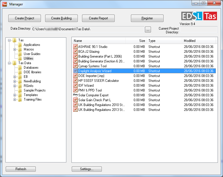
The Daylight Analysis Wizard can be opened using Tas Manager. To do so, open up Tas Manager, navigate to the Utilities folder and then select Daylight Analysis Wizard from the main workspace.
2 The Wizard
2.1 The Select Files Page
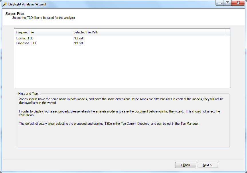
The Select Files Page is the first page of the wizard after the introduction page. Using this page, you will select the existing and proposed T3D files.
To select a T3D file, click on the Select File Path Column for either the Existing T3D row or the Proposed T3D row. This will open up the open file dialog, allowing you to select you file.
There are some requirements on what T3D files can be used for the proposed and existing models. First of all, each file must have at least one assigned zone. If you select a file with no assigned zones then you will receive an error and will be asked to select another file. Also, the latitude and longitude of both the existing and proposed files must match up. If you select existing and proposed files with mis-matching latitudes or longitudes you will receive a warning notifying you of this and telling you that the existing file's coordinates will be used for both files.
Please note that you must select both an existing and proposed t3d file from this page. Without selecting both, you will not be able to progress from this page, and will receive an error telling you to select both.
2.2 The Apply Tags Page
The Apply Tags page is used to create and assign tags to the zones in the model. Tags can be used to apply different daylight calculation properties to a group of zones, or to sort the results in the outputted CSV files. However, it should be noted that using these tags is completely optional. If you wish you can skip creating tags by selecting the next button on the wizard.
There are two different types of tags that can be created on this page, Building Reference tags and Room Use tags. Building Reference tags are intended to be used to report which building the zones belong to, while Room Use tags are intended to be used to denote the intended use of the zone. To make it easier to recognise which tag is being referred to in other areas of the software, Building Reference tags begin with "BR_" while Room Use tags begin with "RU_". You can switch between creating and applying either type of tag by selecting the appropriate radio button in the Tag Type box.
The process to create and apply tags is the same with either type of tag. Tags can be created by clicking on the Add Tag Icon  in the bottom left corner of the screen.
This brings up the New Tag dialog window, which allows you to name your new tag. Upon clicking the OK button on the New Tag dialog, the tag will appear on the box on the left hand side of the screen.
If you wish to remove this tag from the wizard, select it on the left hand side of the screen and press the Delete Tag icon
in the bottom left corner of the screen.
This brings up the New Tag dialog window, which allows you to name your new tag. Upon clicking the OK button on the New Tag dialog, the tag will appear on the box on the left hand side of the screen.
If you wish to remove this tag from the wizard, select it on the left hand side of the screen and press the Delete Tag icon  in the bottom left corner of the screen.
To assign a tag to a zone requires dragging the tag on the left hand side of the screen onto the zone on the right hand side of the screen. One tag can be applied to multiple zones by selecting the zones before dragging the tag over to the right hand side of the screen. Multiple zones can be selected by either holding down the Ctrl key on your keyboard while left clicking on each zone you wish to select, or by holding down the Shift key while selecting the top and bottom zones from a list of zones you wish to select.
The tags created on this page are saved to both the Existing and Proposed T3D files when you press the next button on the wizard. This means that the tags will be re-loaded into the wizard if you wish to run the analysis again on the same files. However, this process will not work if you delete the tags from the T3D files.
2.3 The Default Calculations Settings Page
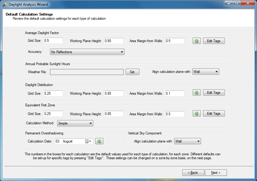
On the Default Calculations Settings page you are able to set the settings used for each type of calculation. These can be set as one default value to be used by all zones, or bespoke values for a group of zones based on the applied tag. This section of the guide will only deal with the settings available on this page. More information about the calculations can be found in Section 4.
For the Average Daylight Factor, Daylight Distribution and Equivalent First Zone calculations you will need to provide the:
- Grid Size - This sets the size of the daylight grid used in the calculations. The smaller the grid, the more accurate the results but the longer the calculation will take, due to the increased number of grid points. The value you enter is the distance between each grid point in metres.
- Working Plane Height - This is the height above the floor, in metres, that the light levels are read at.
- Area Margin from Walls - This sets a margin between the boundary of your space and your lighting grid. This would stop any dark corners in the space from affecting the results. The value entered should be the distance between the grid and the walls, in metres.
There are two ways of setting these values for the zones. The first way is to enter in the values into the appropriate boxes on Default Calculation Settings page. This will then be the default values used for all zones in the model.
If you wish to revert back to the default settings provided by the wizard for these calculations, press the Revert Changes button in that calculation's box. The Revert Changes button is the button with the
green anti-clockwise rotating arrow  icon.
icon.
However, sometimes you may want to use different settings for different zones. For instance you might want to use a higher working plane height for kitchen areas due to the worktops. To set up bespoke values for certain zones, you would apply the daylight settings to a tag. To set daylight settings by tag, you would first need to assign a tag to the zones needing the bespoke settings in the Apply Tags page. Then, on the Default Calculation Settings page click on the Edit Tags button on the calculation you wish to use the bespoke settings with. This will open up the Tag Defaults dialog.
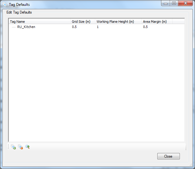
When the Tag Defaults dialog opens, press on the Magnifying Glass icon  . A dialog will appear listing all previously created tags,
all you need to do is select your tag and press the OK button. This will bring the selected tag into the Tag Defaults Dialog, where you can change the calculation settings. If you wish to remove any tag from the Tag Defaults Dialog,
select the tag in question and then press the Delete Tag icon in the bottom left corner of the screen. There is also an Add Tag Icon
in the bottom left corner of the screen, which allows tags to be created from this page. However, any tag created on this page will still need to be assigned to a zone on the
Assign Tag page.
. A dialog will appear listing all previously created tags,
all you need to do is select your tag and press the OK button. This will bring the selected tag into the Tag Defaults Dialog, where you can change the calculation settings. If you wish to remove any tag from the Tag Defaults Dialog,
select the tag in question and then press the Delete Tag icon in the bottom left corner of the screen. There is also an Add Tag Icon
in the bottom left corner of the screen, which allows tags to be created from this page. However, any tag created on this page will still need to be assigned to a zone on the
Assign Tag page.
Any bespoke settings stored in the Tag Defaults dialog are saved in the wizard. This means, if you use the same tag on another project you will not need to re-enter the bespoke daylight settings.
With the Average Daylight Factor and Equivalent First Zone calculations you are also asked for additional information. For the Average Daylight Factor Calculation you are asked to set the accuracy of the calculation from the following settings:
- No Reflectance - No reflected light is accounted for in the calculation. The quickest but least accurate method.
- One Reflectance - Only non reflected light and light reflected off one surface is accounted for in the calculation.
- Many Reflectance - Rays of light are tracked bouncing around the space until a set level of convergence is reached. This is the slowest but most accurate level of analysis.
While with the Equivalent First Zone calculation, you are asked if you want to use the Simple or Geometric calculation method. Both methods are explained in Section 4.4 of this guide.
For the Vertical Sky Component (VSC) and Annual Probable Sunlight Hours (ASPH) calculations you need to decide how you wish to align the calculation plane. There are two options to choose from:
- Wall - With this option the VSC and ASPH calculations are taken from the outside surface of the wall, rather than from where the window pane sits within the wall. This means that the affect of any shading due to the window being recessed within the wall will not be accounted for in the calculation.
- Window Pane - With this option the VSC and ASPH calculations are taken from where the window pane sits within the wall, rather than from the outer surface of the wall. This means that the affect of any shading due to the window being recessed within the wall will be accounted for in the calculation.
The ASPH calculation also requires a weather file to be used to obtain the annual probable sunlight hours for that location. To set a weather file, press the Set button. This will open the Open dialog, where you will need to select a Tas Weather Database file containing the appropriate weather file. With the appropriate weather database selected, the Select Weather File dialog will appear.
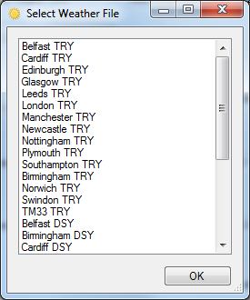
In this dialog, just select the correct weather file and click the OK button. This will then set this file as the weather data used during the ASPH calculation. Please note that a weather file must be selected before trying to run a ASPH calculation, you will receive an error if you try to run a ASPH calculation without weather data selected.
For the Permanent Overshadowing calculation you need to select a day for the calculation to be run on. By default this is set to run on the 21st of March, which is one of the days the spring equinox can fall on.
The date can be changed by clicking on the calendar icon  and choosing the day from the calendar that appears.
2.4 The Calculation Settings Page
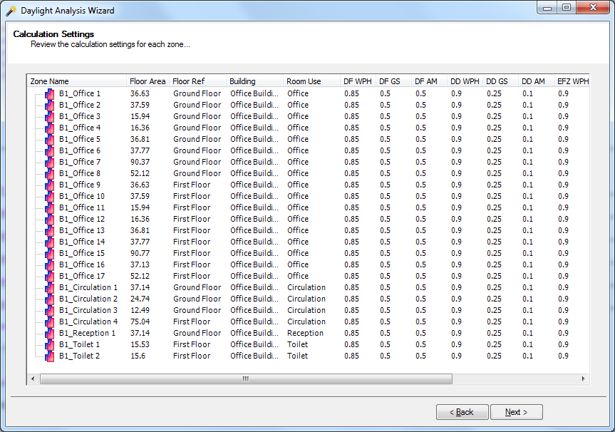
The Calculation Settings page allows you to recap the calculation settings applied to each zone, along with providing the option of turning off certain calculations for certain zones. The page is taken up by a tree view detailing the following information for each zone:
-
Zone Name - The Zone Name column displays the zone's name, but also an icon next to it detailing what model(s) that zone is in. If only a blue zone icon
 is visible,
then the zone is only in the Existing model. If only a red zone icon
is visible,
then the zone is only in the Existing model. If only a red zone icon  is visible, then the zone is only in the Proposed model. If the icon displayed
has both the blue and red zone icons
is visible, then the zone is only in the Proposed model. If the icon displayed
has both the blue and red zone icons  then the zone is in both the Existing and Proposed models.
- Floor Area - The Floor Area column displays the floor area of the zone. Please note that for the floor areas to be reported in the wizard, an Analysis View must have been built in the 3D Modeller for both the Proposed and Existing Buildings. If either one does not have an analysis view stored in the respective 3D Modeller file, the floor area column will display "No Analysis Model".
- Floor Ref - The Floor Ref Column reports the storey the zone is used on in the respective 3D Modeller files.
- Building - The Building column reports the Building Reference tag applied to the zone, if one has been applied.
- Room Use - The Room Use column reports the Room Use tag applied to the zone, if one has been applied.
- DF WPH - The DF WPH column reports the working plane height to be used on the Average Daylight Factor calculation. If the calculation is not set to be carried out for a particular zone, a hyphen will appear here.
- DF GS - The DF GS column reports the grid size to be used on the Average Daylight Factor calculation. If the calculation is not set to be carried out for a particular zone, a hyphen will appear here.
- DF AM - The DF AM column reports the area margin from walls to be used on the Average Daylight Factor calculation. If the calculation is not set to be carried out for a particular zone, a hyphen will appear here.
- DD WPH - The DD WPH column reports the working plane height to be used on the Daylight Distribution calculation. If the calculation is not set to be carried out for a particular zone, a hyphen will appear here.
- DD GS - The DD GS column reports the grid size to be used on the Daylight Distribution calculation. If the calculation is not set to be carried out for a particular zone, a hyphen will appear here.
- DD AM - The DD AM column reports the area margin from walls to be used on the Daylight Distribution calculation. If the calculation is not set to be carried out for a particular zone, a hyphen will appear here.
- EFZ WPH - The EFZ WPH column reports the working plane height to be used on the Equivalent First Zone calculation. If the calculation is not set to be carried out for a particular zone, a hyphen will appear here.
- EFZ GS - The EFZ GS column reports the grid size to be used on the Equivalent First Zone calculation. If the calculation is not set to be carried out for a particular zone, a hyphen will appear here.
- EFZ AM - The EFZ AM column reports the area margin from walls to be used on the Equivalent First Zone calculation. If the calculation is not set to be carried out for a particular zone, a hyphen will appear here.
- VSC - The VSC column reports if the Vertical Sky Component calculation will be carried out on this zone. If the calculation is to be carried out, the field will report "On", while it will report "Off" if no calculation is due to take place.
- PO - The PO column reports if the Permanent Overshadowing calculation will be carried out on this zone. If the calculation is to be carried out, the field will report "On", while it will report "Off" if no calculation is due to take place. Please note that the Permanent Overshadowing calculation is only applicable for external zones.
- APSH - The APSH column reports if the Annual Probable Sunlight Hours calculation will be carried out on this zone. If the calculation is to be carried out, the field will report "On", while it will report "Off" if no calculation is due to take place.
The information within the tree view can be reported in ascending or descending order, for any column in the tree view, by clicking on the column headers.
To turn any of the calculations on or off can be done by selecting the applicable zone and then right clicking to bring up the contextual menu.
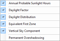
On the contextual menu, any calculation with a tick next to it is currently being run for the zone, while any zone without a tick is not currently being run. To alter the calculation's state, just left click over it.
Switching the calculation from on to off, or vice versa, can be done for multiple zones at once, by selecting the zones before right clicking. Multiple zones can be selected by either holding down the Ctrl key on your keyboard while left clicking on each zone you wish to select, or by holding down the Shift key while selecting the top and bottom zones from a list of zones you wish to select.
2.5 Save and Simulate
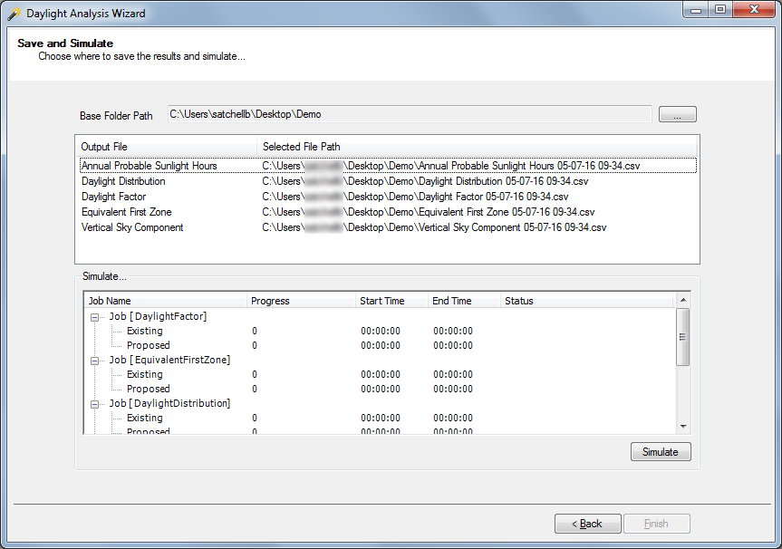
The Save and Simulate page is the final page of the wizard. From this page we can start the simulation, and also set the location where the results from the simulation are saved.
The wizard produces CSV files for each calculation type detailing the results for each zone. These CSV files can be opened in many different programs, for example Excel, where the results can viewed. By default, Tas will save the CSV files to the same location as the Proposed T3D file. However this can be changed globally, i.e. for all CSV files at once, by changing the Base Folder Path. The output paths can also be changed on a CSV by CSV basis. To do this, click on the current path for the CSV in question in the Selected File Path column. This will bring up the Save As dialog, allowing you to select the location you wish that CSV file to be saved to.
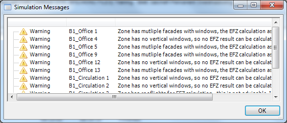
When the page first appears, the simulate box will contain no jobs. However, after a few seconds, jobs will start appearing depending on how many calculations the software needs to do. Once the software, has allocated all jobs, the Simulate button will be enabled. Pressing the Simulate button will start the software off running these calculations, with the Simulate box providing updates on which calculations are currently running. Once the calculations are complete, and there are no issues to be notified of, the Finish button will be enabled and the wizard will close upon pressing the close button. However, if there were any issues with the simulation, the Simulation Messages dialog will appear to notify you of the issues.
The following is a description of what each notification means, and common causes of the issue:
-
 Error - DoWindowPoint calculation failed. Usually due to no transparent windows. This error means that the software was unable to complete a window point calculation,
which is required for the Vertical Sky Component and Annual Probable Sunlight Hours calculation. The common cause for this is having a proposed or existing model without any transparent windows.
Error - DoWindowPoint calculation failed. Usually due to no transparent windows. This error means that the software was unable to complete a window point calculation,
which is required for the Vertical Sky Component and Annual Probable Sunlight Hours calculation. The common cause for this is having a proposed or existing model without any transparent windows.
-
Error - [Zone Name] - Error producing ADF Output. This error means that the software was not able to produce any CSV output for the Average Daylight Factors calculation.
This error is rare and doesn't have a common cause, so if you do receive it please send your files to support@edsl.net detailing the inputs you used in the wizard to reproduce this error.
-
Error - [Zone Name] - Error producing APSH Output. This error means that the software was not able to produce any CSV output for the Annual Probable Sunlight Hours calculation.
This error is rare and doesn't have a common cause, so if you do receive it please send your files to support@edsl.net detailing the inputs you used in the wizard to reproduce this error.
-
Error - [Zone Name] - Error producing DD Output. This error means that the software was not able to produce any CSV output for the Daylight Distribution calculation.
This error is rare and doesn't have a common cause, so if you do receive it please send your files to support@edsl.net detailing the inputs you used in the wizard to reproduce this error.
-
Error - [Zone Name] - Error producing EFZ Output. This error means that the software was not able to produce any CSV output for the Equivalent First Zone calculation.
This error is rare and doesn't have a common cause, so if you do receive it please send your files to support@edsl.net detailing the inputs you used in the wizard to reproduce this error.
-
Error - [Zone Name] - Error producing PO Output. This error means that the software was not able to produce any CSV output for the Permanent Overshadowing calculation.
This error is rare and doesn't have a common cause, so if you do receive it please send your files to support@edsl.net detailing the inputs you used in the wizard to reproduce this error.
-
Error - [Zone Name] - Error producing VSC Output. This error means that the software was not able to produce any CSV output for the Vertical Sky Component calculation.
This error is rare and doesn't have a common cause, so if you do receive it please send your files to support@edsl.net detailing the inputs you used in the wizard to reproduce this error.
-
 Warning - [Zone Name] - Unable to calculate a daylight factor (cannot calculate a daylight grid. This warning appears when it was not possible to calculate a daylight factor
for the reported zone. Common causes for this is the zone has no access to daylight, which means a daylight calculation should not be carried out, or that the zone is too small to create a daylight grid using the entered
daylight settings.
Warning - [Zone Name] - Unable to calculate a daylight factor (cannot calculate a daylight grid. This warning appears when it was not possible to calculate a daylight factor
for the reported zone. Common causes for this is the zone has no access to daylight, which means a daylight calculation should not be carried out, or that the zone is too small to create a daylight grid using the entered
daylight settings.
-
Warning - [Zone Name] - Zone has multiple facades with windows, the EFZ calculation assumes only one facade having a window. This warning when you try to do a
Equivalent First Zone calculation on a zone with windows on multiple facades. The Equivalent First Zone calculation is defined based off only one facade having a window, so having multiple facades with windows
will cause problems with the calculation. Please see Section 4.4 for more information on the Equivalent First Zone calculation.
-
Warning - [Zone Name] - Zone has no vertical windows, so no EFZ result can be calculated. This warning appears when you try to do a Equivalent First Zone calculation on
a zone with no vertical windows. As the calculation is defined for a window in a facade, the calculation cannot be carried out on this space and thus no results are reported for this zone in the CSV output. Please see
Section 4.4 for more information on the Equivalent First Zone calculation.
-
Warning - [Zone Name] - Zone has rooflights for EFZ calculation - this is not advisable. Interpret results carefully. This warning appears when you try to
do a Equivalent First Zone calculation on a zone with rooflights. The Equivalent First Zone calculation is intended for vertical windows on a facade, not for rooflights. Please see
Section 4.4 for more information on the Equivalent First Zone calculation.
-
Warning - [Zone Name] - A window is present in the proposed but not the existing. This warning appears when a zone that appears in both the existing and proposed models,
has a window that only appears in the proposed model and not the existing model. While this may be intended, it will impact the results and the comparison between the two models.
-
Warning - [Zone Name] - A window is present in the existing but not the proposed. This warning appears when a zone that appears in both the existing and proposed models,
has a window that only appears in the proposed model and not the existing model. While this may be intended, it will impact the results and the comparison between the two models.
3. The CSV Output
3.1 Annual Probable Sunlight Hours
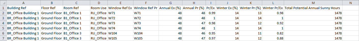
The Annual Probable Sunlight Hours CSV provides the results from the Annual Probable Sunlight Hours calculation. For each zone, the following results are outputted:
- Building Ref - Reports the Building Reference tag applied to the zone.
- Floor Ref - Reports the storey the zone can be found on within the models.
- Room Ref - Reports the zone name.
- Room Use - Reports the Room Use tag applied to the zone.
- Window Ref Ex - Reports the Window Reference assigned to the window in the existing model by the 3D Modeller.
- Window Ref Pr - Reports the Window Reference assigned to the window in the proposed model by the 3D Modeller.
- Annual Ex - Reports the number of hours over the year that the window in the existing model received direct sunlight as a percentage of the total potential annual sunny hours. If the zone, or the window, is not part of the existing model, the output will state "Not Calculated".
- Annual Pr - Reports the number of hours over the year that the window in the proposed model received direct sunlight as a percentage of the total potential annual sunny hours. If the zone, or the window, is not part of the proposed model, the output will state "Not Calculated".
- Pr/Ex - Reports the Annual Pr value divided by the Annual Ex value. If the Annual Ex value is zero, the words "N/A" will appear here instead as division by zero is undefined. If the zone only appears in either the proposed or the existing model, then the words "Not Calculated" will appear here as the comparison is not valid.
- Winter Ex - Reports the number of hours over the winter that the window in the existing model received direct sunlight as a percentage of the total potential annual sunny hours. If the zone, or the window, is not part of the existing model, the output will state "Not Calculated".
- Winter Pr - Reports the number of hours over the winter that the window in the proposed model received direct sunlight as a percentage of the total potential annual sunny hours. If the zone, or the window, is not part of the proposed model, the output will state "Not Calculated".
- Winter Pr/Ex - Reports the Winter Pr value divided by the Winter Ex value. If the Winter Ex value is zero, the words "N/A" will appear here instead as division by zero is undefined. If the zone only appears in either the proposed or the existing model, then the words "Not Calculated" will appear here as the comparison is not valid.
- Total Potential Annual Sunny Hours - Reports the number of annual sunny hours calculated from the selected weather file. This is the potential maximum number of sunny hours the window can receive.
3.2 Average Daylight Factor CSV
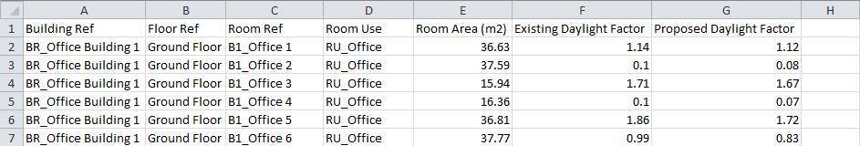
The Average Daylight Factor CSV provides the results from the Average Daylight Factor calculation. For each zone, the following results are outputted:
- Building Ref - Reports the Building Reference tag applied to the zone.
- Floor Ref - Reports the storey the zone can be found on within the models.
- Room Ref - Reports the zone name.
- Room Use - Reports the Room Use tag applied to the zone.
- Room Area - Reports the room's floor area, in square metres.
- Existing Daylight Factor - Reports the average daylight factor for the zone in the existing model. If the zone is not part of the existing model, the output will state "Not Calculated".
- Proposed Daylight Factor - Reports the average daylight factor for the zone in the proposed model. If the zone is not part of the proposed model, the output will state "Not Calculated".
3.3 Daylight Distribution CSV
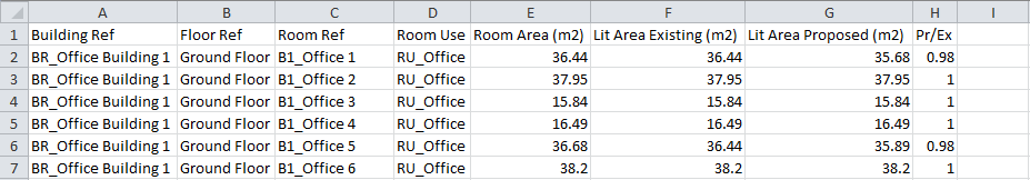
The Daylight Distribution CSV provides the results from the Daylight Distribution calculation. For each zone, the following results are outputted:
- Building Ref - Reports the Building Reference tag applied to the zone.
- Floor Ref - Reports the storey the zone can be found on within the models.
- Room Ref - Reports the zone name.
- Room Use - Reports the Room Use tag applied to the zone.
- Room Area - Reports the room's floor area, in square metres.
- Lit Area Existing - Reports the area, in square metres, of the zone in the existing model that can see the sky at the working plane height through any windows in the space. If the zone is not part of the existing model, the output will state "Not Calculated".
- Lit Area proposed - Reports the area, in square metres, of the zone in the proposed model that can see the sky at the working plane height through any windows in the space. If the zone is not part of the proposed model, the output will state "Not Calculated".
- Pr/Ex - Reports the Lit Area Proposed divided by the Lit Area Existing. If the Lit Area Existing value is zero, the words "N/A" will appear here instead as division by zero is undefined. If the zone only appears in either the proposed or the existing model, then the words "Not Calculated" will appear here as the comparison is not valid.
3.4 Equivalent First Zone CSV
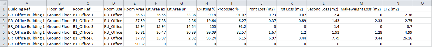
The Equivalent First Zone CSV provides the results from the Equivalent First Zone calculation. For each zone, the following results are outputted:
- Building Ref - Reports the Building Reference tag applied to the zone.
- Floor Ref - Reports the storey the zone can be found on within the models.
- Room Ref - Reports the zone name.
- Room Use - Reports the Room Use tag applied to the zone.
- Room Area - Reports the room's floor area, in square metres.
- Lit Area Existing - Reports the area, in square metres, of the zone in the existing model that has an illuminance greater than or equal to 0.2% of the sky factor at the working plane height. If the zone is not part of the existing model, the output will state "Not Calculated".
- Lit Area proposed - Reports the area, in square metres, of the zone in the proposed model that has an illuminance greater than or equal to 0.2% of the sky factor at the working plane height. If the zone is not part of the proposed model, the output will state "Not Calculated".
- Existing % - Reports the lit area in the existing model as a percentage of the total floor area. If the zone is not part of the existing model, the output will state "Not Calculated".
- Proposed % - Reports the lit area in the proposed model as a percentage of the total floor area. If the zone is not part of the proposed model, the output will state "Not Calculated".
- Front Loss - Reports the loss in area, in square meters, of the front zone in the room between the existing and proposed models. If the room is not part of either the existing or proposed model, the output will state "Not Calculated".
- First Loss - Reports the loss in area, in square meters, of the first zone in the room between the existing and proposed models. If the room is not part of either the existing or proposed model, the output will state "Not Calculated".
- Second Loss - Reports the loss in area, in square meters, of the second zone in the room between the existing and proposed models. If the room is not part of either the existing or proposed model, the output will state "Not Calculated".
- Makeweight Loss - Reports the loss in area, in square meters, of the makeweight zone in the room between the existing and proposed models. If the room is not part of either the existing or proposed model, the output will state "Not Calculated".
- EFZ - Reports the Equivalent First Zone value calculated from the different losses and their weights.
3.5 Permanent Overshadowing CSV

The Permanent Overshadowing CSV provides the results from the Permanent Overshadowing calculation. For each zone, the following results are outputted:
- Building Ref - Reports the Building Reference tag applied to the zone.
- Floor Ref - Reports the storey the zone can be found on within the models.
- Amenity Ref - Reports the external zone's name.
- Amenity Area - Reports the area of the external zone, in square metres.
- Lit Area Existing - Reports the area, in square metres, of the zone in the existing model that receives sunlight for at least 2 hours on the 21st of March. If the zone is not part of the existing model, the output will state "Not Calculated".
- Lit Area Proposed - Reports the area, in square metres, of the zone in the proposed model that receives sunlight for at least 2 hours on the 21st of March. If the zone is not part of the proposed model, the output will state "Not Calculated".
- Existing % - Reports the lit area in the existing model as a percentage of the total floor area. If the zone is not part of the existing model, the output will state "Not Calculated".
- Proposed % - Reports the lit area in the proposed model as a percentage of the total floor area. If the zone is not part of the proposed model, the output will state "Not Calculated".
- Pr/Ex - Reports the Lit Area Proposed divided by the Lit Area Existing. If the Lit Area Existing value is zero, the words "N/A" will appear here instead as division by zero is undefined. If the zone only appears in either the proposed or the existing model, then the words "Not Calculated" will appear here as the comparison is not valid.
3.6 Vertical Sky Component CSV
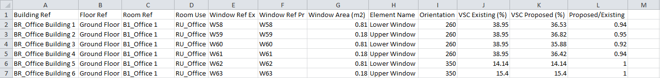
The Vertical Sky Component CSV provides the results from the Vertical Sky Component calculation. For each zone, the following results are outputted:
- Building Ref - Reports the Building Reference tag applied to the zone.
- Floor Ref - Reports the storey the zone can be found on within the models.
- Room Ref - Reports the zone name.
- Room Use - Reports the Room Use tag applied to the zone.
- Window Ref Ex - Reports the Window Reference assigned to the window by the 3D Modeller in the existing model.
- Window Ref Pr - Reports the Window Reference assigned to the window by the 3D Modeller in the proposed model.
- Window Area - Reports the area of the window.
- Element Name - Reports the name of the window from the 3D modeller file.
- Orientation - Reports the orientation the window is facing.
- VSC Existing (%) - Reports the vertical sky component for the window in the existing model. If the window or zone does not exist in the proposed model, the output will state "Not Calculated".
- VSC Proposed (%) - Reports the vertical sky component for the window in the proposed model. If the window or zone does not exist in the proposed model, the output will state "Not Calculated".
- Proposed / Existing - Reports the Proposed CSV value divided by the Existing CSV value.
4. Calculation Details
This section details how the calculations are performed internally.
4.1 Annual Probable Sunlight Hours
The number of hours during which direct sunlight reaches an unobstructed ground for a particular location during a year is referred to as the number of 'annual sunlight hours'. If the number of annual sunlight hours for a location is measured and averaged over many years, the result is the 'annual probable sunlight hours' metric; that is, the number of hours an unobstructed ground is likely to receive direct sunlight during a year.
'BS 8206-2: Lighting for Buildings' gives recommendations regarding the number of annual probable sunlight hours that a window should receive in order to have a good probability of being sufficiently lit. In particular, it quantifies the proportions of APSH hours that a window should receive during the winter and summer months.
Common calculation methodology
'BR209 Site Layout Planning for Daylight and Sunlight' provides a method of estimating the APSH figures for a window using 'sunlight availability indicators'. These were produced in BRE document CP 75/75 'Availability of sunshine' using weather data between 1959-1968 for three locations in the UK. To use this method, the sunlight availability indicator closest to the development (London, Manchester or Glasgow/Edinburgh) would be selected and the proposed development would be drawn onto this diagram. The diagram has 100 points, each point representing 1% of annual probable sunlight hours. The number of unobstructed points is then totalled and multiplied by the annual unobstructed total for each location.
Tas methodology
Using the Tas daylight simulation engine and weather databases, the number of annual probable sunlight hours for a window can be estimated much more accurately. Using the daylight analysis wizard, when an APSH calculation is performed for a window, the wizard analyses the weather data for each hour of the year to determine if it is sunny. If it is a potential sunny hour, the wizard then performs a 'no-bounce' direct daylight calculation for that window taking into consideration surrounding geometry, to see whether the window receives direct sunlight in the centre of its pane.
The daylight analysis wizard uses the definition of 'bright sunshine' given in 'Guide to Meteorological Instruments and Methods of Observation' to determine whether an hour is sunny. If the direct solar irradiance is greater than 120W/m2, the hour is considered to be a probable sunlight hour.
The number of annual probable sunlight hours calculated using the above methodology is given below:
| CIBSE 2005 TRY | EDSL Tas | BRE Availability of Sunshine |
|---|---|---|
| Belfast | 1464 | - |
| Cardiff | 1846 | - |
| Edinburgh | 1248 | 1267 |
| Glasgow | 1465 | 1267 |
| Leeds | 1358 | - |
| London | 1478 | 1486 |
| Manchester | 1449 | 1392 |
| Newcastle | 1396 | - |
| Nottingham | 1744 | - |
| Plymouth | 1803 | - |
| Southampton | 1674 | - |
| Birmingham | 1473 | - |
| Norwich | 1763 | - |
| Swindon | 1725 | - |
The calculations are performed using a CIE overcast sky.
4.2 Average Daylight Factor
The daylight factor of a space is the ratio of the amount of natural light inside to outside. It is calculated on a horizontal plane inside the building. The height of the horizontal plane is called the working plane height and for a school, would be the height of the desks in the room.
Light can reach the inside of a space:
- Directly from the sky
- After reflecting off something outside
- After reflecting off something inside
To calculate daylight factors accurately without directly measuring requires adding all of the light reaching the working plane from each of the sources listed above.
Calculating Average Daylight Factor
BRE Guide 209
The Building Research Establishment (BRE) developed a way of estimating the amount of light reaching the working plane coming directly from the sky:
Where:
- T is the diffuse visible transmittance of the glazing
- M is a maintenance factor
- Aw is the glazed area
- A is the total area of room surfaces
- R is the average reflectance of surfaces in the room
- θ is the angle of visible sky (degrees)
This does not account for:
- Light reaching the space after reflecting upon outside and inside surfaces.
- The layout of a space.
- Complex outside obstructions
Daylight Analysis Wizard
You can use the daylight analysis wizard to calculate the average daylight factor based on light directly from the sky, (similar to the BRE method), or by including reflections from outside surfaces.
The Tas software uses a radiosity method to determine the illuminance of a surface. The contribution of reflected, absorbed and transmitted light from the different surfaces that are in the 3D Tas model can be considered.
- To only include light arriving in the space directly from the sky, select the ‘No Reflections’ accuracy setting.
- To include light that reflects once off a surface before reaching the working plane, select ‘One Bounce’.
- To include light that reflects many times off of many surfaces before reaching the working plane, select ‘Many Bounces’.
The ‘No Reflections’ daylight factor calculation is very fast. The ‘Many Bounces’ calculation can take a lot longer to complete, so you should consider when to use this carefully. You may wish to use the ‘Many Bounces’ option when a space is close to reaching a desired daylight factor.
4.3 Daylight Distribution
Daylight Distribution considers the area of a room that cannot see the sky at the working plane height, and is closely related to the 'no sky line'.
To calculate daylight distribution, a 'no bounce' direct daylight calculation is performed using the Tas daylighting engine. The calculation assumes the CIE clear sky. Glazing is assumed to be completely transparent.
Following the daylight calculation, the ratio of the number of grid-points with lux values greater than 0 to the total number of grid-points is calculated. This is multiplied by the total area of the zone to estimate the lit area.
4.4 Equivalent First Zone
An equivalent first zone calculation attempts to determine the area within a space that is adequately lit and quantify the impact of a change to that area. A loss of lit area near the façade containing windows should be considered more significant than a loss of lit area toward the far side of a zone.
Based on methodologies devised in the 1920s, a point on the working plane is considered to be 'adequately lit' if the illuminance is equal to or greater than 0.2% of the sky factor. Though it is now believed that 0.2% Sky Factor is below the practical minimum, it is still used for the purposes of equivalent first zone calculations.
The Equivalent First Zone calculation is ill defined, and there are two conflicting definitions in circulation. Both have been implemented in the wizard, and are referred to as the 'simple' method and the 'geometric' method. For an equivalent first zone calculation, a room lit from a single façade is split into four sections- the first 25% of the room area is called the 'front zone'. The next 25% is known as the 'first zone', the next 25% is the 'second zone' and the final 25% is the 'makeweight zone'. A loss of adequately lit area in the front zone is given a weighting factor of 1.5. A loss in the first zone has a weighting factor of 1. A loss in the second zone has a weighting factor of 0.5 and a loss in the makeweight zone has a weighting factor of 0.25.
One definition of Equivalent First Zone defines the four sections as 'notional' areas, which are not physical areas in the space. Another definition splits the room into quarters depending on the distance from the lit façade. In wizard, the former corresponds to the 'simple' method and the latter corresponds to the 'geometric', as the latter depends on the geometry of the room and the former does not.
The image below shows how a rectangular room would be divided using the geometric method.
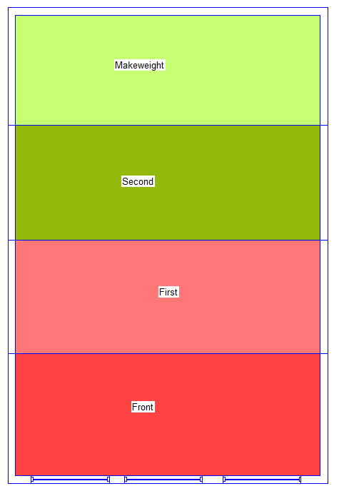
Using the above weighting factors an 'equivalent area' is calculated which is referred to as the 'Equivalent First Zone'.
Tas Calculation Details: Geometric
When using the daylight analysis wizard to calculate the equivalent first zone area, a daylight simulation is performed using the Tas daylighting engine. The calculation uses a uniform CIE sky and considers direct light only; no reflections are considered. The simulation is a sky-only simulation. The working plane height, grid size and area margin from walls are specified by the user.
Once the daylight calculation has been performed, the zone is notionally split into 4 areas depending on the distance from the lit façade. For each one of these notional zones, the fraction of points with illuminances greater than or equal to 0.2% of the sky factor is calculated and multiplied by 1/4 of the total zone area to determine the lit area in that zone. The areas are then combined in a weighted average using the weighting factors given above.
Important!
Equivalent first zone calculations using the geometric method are ill defined for non-rectangular rooms. They are also ill defined for rooms lit from multiple façades. For a room that is lit from multiple façades, the wizard will warn the user and proceed by splitting the room up into the first, front, second and makeweight areas based upon the distance perpendicular to the plane of the first window the wizard finds in the zone.
Below is an example of how a zone will be notionally sub-zoned if it is an unusual shape with an unusual placement of windows:
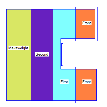
As a result of this, the way in which the wizard will classify regions of a zone should be considered carefully before attempting EFZ calculations on non-rectangular rooms. It may be more appropriate to re-zone oddly shaped rooms to circumvent any issues, for example the above could be rezoned as follows:
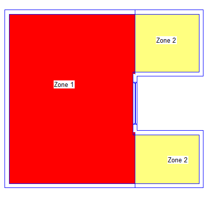
Zone 2 could then be excluded from the calculation and an EFZ calculation performed on Zone 1.
It is also important to note that EFZ calculations are ill defined for windows in sloped walls and not applicable to zones with rooflights. As windows in sloped walls are modelled with rooflights in Tas, there is nothing preventing a user from attempting EFZ calculations on a zone with rooflights. Caution is advised.
Tas Calculation Details: Simple
Calculating the equivalent first zone using the simple method can be achieved using just the total room area, the lit are before and the lit area after. A 100m² room that is lit to 50% is assumed to have all light in the front zone and the first zone, but complete darkness to the second and makeweight zones. A 100m² room with a lit area of 25m² is assumed to have only the front zone fully lit.
The second zone loss and makeweight zone loss are combined together into one category depending on whether the loss is actionable. The loss is actionable if less than 50% of the room is lit in the proposed model. If the loss is actionable, the second zone loss and makeweight loss are summed and considered second zone loss. If not actionable, the second zone loss is moved to the makeweight loss.
4.5 Permanent Overshadowing
Permanent overshadowing considers the impact of shadows cast by buildings on outside spaces.
BRE Guide 209 recommends:
- At least 1/2 the space should have at least 2 hours of sunlight on 21st March.
- Failing the above, the area receiving at least 2 hours of sun should not be less than 0.8x its former value.
The daylight analysis wizard calculates the permanent overshadowing results by:
- Performing a ‘No Bounce’ calculation for each hour the sun is up.
- For each gridpoint from each calculation, checking to see if it receives daylight (if illuminance > 0 lux)
- Multiplying the fraction of points that receive at least 2 hours of daylight with the area of the space.
The permanent overshadowing calculating is performed with a CIE Clear Sky, Sun Only with No Reflection Bounces.
4.6 Vertical Sky Component
The ‘vertical sky component’ of a window relates to the amount of sky the window can receive direct light from. It is the ratio of the direct sky illuminance reaching the centre of the window pane to the horizontal illuminance under a clear CIE overcast sky.
For a completely unobstructed vertical surface, the maximum VSC value is ~40%.
The Daylight Analysis Wizard calculates the vertical sky component of a window using a CIE Overcast Sky, Sky and Sun, with No Reflections. The calculation takes into consideration obstructions from surrounding obstructions, providing they have been included in the 3D model.