Airside Systems
The setups of the airside systems created by the Systems wizard are explained in this section. Systems can be set up to comply with 90.1 versions 2007, 2010, 2013, 2016, 2019, or 2022. For each system type there is an explanation of how the system complies with the 90.1 guidance. Points in bold are things that the user must check for themselves and enter data accordingly – compliance with the other points is either dealt with by the system setup itself as created by the wizard, or by running the 90.1 Airside Efficiency tool and 90.1 Plant Efficiency Tool.
Note that the flow components (fans, dampers, and economiser) and the controllers related to these components should not be removed from VAV-type systems as this may cause unintended and incorrect behaviour.
Baseline Airside System Selection
Generally speaking, the baseline system will be determined by the building size and either fuel type (for 90.1-2007 and 90.1-2010) or climate zone (for 90.1 versions 2013, 2016, 2019, and 2022). It is advised that users check early on in the project what system types they can expect to use, as appropriate grouping of zones can save a lot of time at the TPD stage of the project.
The tables for looking up baseline system types are reproduced below (see the 90.1 document for more details). Note that exceptions may apply depending on the version of 90.1 being used and details of the building operation. For instance, areas with gains or schedules very different to the rest of the building may have to be assigned to different systems. It is recommended that the user checks for relevant exceptions in Appendix G before creating their systems.
90.1-2007 Table G3.1.1A
Building Type |
Fossil Fuel, Fossil/Electric Hybrid, Purchased Heat |
Electric and Other |
|---|---|---|
Residential |
System 1 |
System 2 |
Non-residential, 3 floors or less, <25,000 ft2 (2,323 m2) |
System 3 |
System 4 |
Non-residential, 4-5 floors & < 25,000 ft2 (2,323 m2) OR 5 floors or less & 25,000 – 150,000 ft2 (2,323 – 13,935 m2) |
System 5 |
System 6 |
Non-residential, >5 floors or >150,000 ft2 (13,935 m2) |
System 7 |
System 8 |
90.1-2010 Table G3.1.1A
Building Type |
Fossil Fuel, Fossil/Electric Hybrid, Purchased Heat |
Electric and Other |
|---|---|---|
Residential |
System 1 |
System 2 |
Non-residential, 3 floors or less, <25,000 ft2 (2,323 m2) |
System 3 |
System 4 |
Non-residential, 4-5 floors & < 25,000 ft2 (2,323 m2) OR 5 floors or less & 25,000 – 150,000 ft2 (2,323 – 13,935 m2) |
System 5 |
System 6 |
Non-residential, >5 floors or >150,000 ft2 (13,935 m2) |
System 7 |
System 8 |
Heated only storage |
System 9 |
System 10 |
90.1-2013 Table G3.1.1-3
Building Type |
Climate Zones 3b, 3c, and 4-8 |
Climate Zones 1-3a |
|---|---|---|
Residential |
System 1 |
System 2 |
Public assembly <120,000 ft2 (11,148 m2) |
System 3 |
System 4 |
Public assembly ≥ 120,000 ft2 (11,148 m2) |
System 12 |
System 13 |
Non-residential, 3 floors or less, <25,000 ft2 (2,323 m2) |
System 3 |
System 4 |
Non-residential, 4-5 floors & < 25,000 ft2 (2,323 m2) OR 5 floors or less & 25,000 – 150,000 ft2 (2,323 – 13,935 m2) |
System 5 |
System 6 |
Non-residential, >5 floors or >150,000 ft2 (13,935 m2) |
System 7 |
System 8 |
Heated only storage |
System 9 |
System 10 |
Retail and 2 floors or fewer |
System 3 |
System 4 |
90.1-2016 & 90.1-2019 Table G3.1.1-3
Building Type |
Climate Zones 3b, 3c, and 4-8 |
Climate Zones 1-3a |
|---|---|---|
Residential |
System 1 |
System 2 |
Public assembly <120,000 ft2 (11,148 m2) |
System 3 |
System 4 |
Public assembly ≥ 120,000 ft2 (11,148 m2) |
System 12 |
System 13 |
Heated only storage |
System 9 |
System 10 |
Retail and 2 floors or fewer |
System 3 |
System 4 |
Non-residential, 3 floors or less, <25,000 ft2 (2,323 m2) |
System 3 |
System 4 |
Non-residential, 4-5 floors & < 25,000 ft2 (2,323 m2) OR 5 floors or less & 25,000 – 150,000 ft2 (2,323 – 13,935 m2) |
System 5 |
System 6 |
Non-residential, >5 floors or >150,000 ft2 (13,935 m2) |
System 7 |
System 8 |
90.1-2022 G3.1.1-3
Building Type |
Climate Zones 3b, 3c, and 4-8 |
Climate Zones 1-3a |
|---|---|---|
Residential |
System 1 |
System 2 |
Public assembly <120,000 ft2 (11,148 m2) |
System 3 |
System 4 |
Public assembly ≥ 120,000 ft2 (11,148 m2) |
System 12 |
System 13 |
Heated only storage |
System 9 |
System 10 |
Retail and 2 floors or fewer |
System 3 |
System 4 |
Hospital, >5 floors or >150,000 ft2 (13,935 m2) |
System 7 |
System 7 |
Hospital - all other |
System 5 |
System 5 |
Non-residential, 3 floors or fewer, <25,000 ft2 (2,323 m2) |
System 3 |
System 4 |
Non-residential, 4-5 floors or fewer, <25,000 ft2 (2,323 m2) |
System 5 |
System 6 |
Non-residential, 5 floors or fewer & 25,000 – 150,000 ft2 (2,323 – 13,935 m2) |
System 5 |
System 6 |
Non-residential, >5 floors or >150,000 ft2 (13,935 m2) |
System 7 |
System 8 |
Heating and Cooling types for each baseline system
Baseline System |
Heating Type |
Cooling Type |
|---|---|---|
1 |
Hot Water |
Heat Pump (PTAC) |
2 |
Heat Pump |
Heat Pump (PTHP) |
3 |
Furnace |
Heat Pump (Rooftop AC) |
4 |
Heat Pump |
Heat Pump (Rooftop HP) |
5 |
Hot Water |
Heat Pump (Rooftop HP) |
6 |
Electric Resistance |
Heat Pump (Rooftop HP) |
7 |
Hot Water |
Cold Water |
8 |
Electric Resistance |
Cold Water |
9 |
Furnace |
N/A |
10 |
Electric Resistance |
N/A |
11 |
Depends on Proposed Heating |
Cold Water |
12 |
Hot Water |
Cold Water |
13 |
Electric Resistance |
Cold Water |
Details of Baseline Airside Systems
Systems 1-4
Systems 1-4 are set up to match the requirements of 90.1 versions 2007, 2010, 2013, 2016, 2019, & 2022.
System 3 is shown below both with controllers, and with controllers hidden:
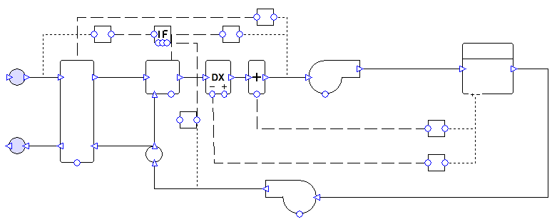
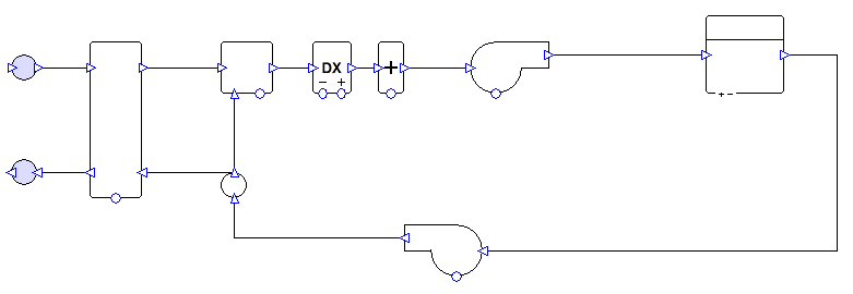
System Overview
One system is created per zone.
Exchanger
By default, the system has a heat recovery unit with 50% enthalpy efficiency (50% sensible efficiency, 50% latent efficiency – enthalpy method). The exchanger is controlled to minimise the load on the coils.
The user should run the 90.1 Airside Efficiency Tool to determine whether or not the system will use an exchanger.
Mixing box
Systems 1 and 2 have a mixing box which allows only the minimum rate of fresh air into the system.
Systems 3 and 4 have an economiser controlled to reduce the load on the coils while providing at least the minimum fresh air requirement. When a specified temperature setpoint is reached the economiser is shut off and provides only the minimum requirement of fresh air. Outside of occupied hours, outside air is only brought into the system if doing so will reduce load on the coils.
Coils
The heating and cooling types are determined by the system type description in Appendix G (see compliance section for details). The system’s heating capacity is oversized by 25%, while the cooling capacity is oversized by 15%. It is possible to change these sizing fractions in the wizard. The coils are controlled to meet the zone’s heating and cooling demands.
Fans
Fans are constant volume. Fans are on a schedule set to run whenever the zone has occupancy or a heating or cooling requirement. The flow rates are sized on a supply-air-to-room-temperature difference of 20°F (11.11°C).
The user should change the fan efficiency and pressure values from the values assigned by the wizard. The 90.1 Airside Efficiency Tool speeds up the process of calculating and assigning the correct values.
Compliance with 90.1 versions 2007, 2010, 2013, 2016, 2019, and 2022
Section 6.4.3.4.3 (2007), 6.4.3.4.2 (2010, 2013, 2016, 2019, & 2022): The wizard sets up the economiser for systems 3 and 4 so that outside of occupied hours outside air is only brought into the system if doing so would reduce the load on the coils. (To shut off outside air altogether in unoccupied hours, the user would change the economiser component “mode when off” property from “No Minimum” to “Recirc”.)
Section G3.1.1 (2007, 2010, 2013, 2016, & 2019), G3.2.1.3 (2022): The wizard creates a separate system for each zone.
Table G3.1 part 4: The wizard sets up the fans to run on hours when there is occupancy or a requirement (in the TSD) for heating or cooling. See also section G3.1.2.4 (2007, 2016, & 2019) or G3.1.2.5 (2010 & 2013).
Table G3.1.1.B (2007 & 2010), G3.1.1-4 (2013, 2016, 2019, & 2022): The wizard creates constant air volume systems with heating and cooling matching the types specified in the table.
Section G3.1.2.1 (2007, 2010, 2013, 2016, & 2019), G3.2.2.1 (2022): The user should run the 90.1 Plant Efficiency Tool to ensure that equipment efficiencies are set in accordance with the relevant sections or tables (depending on the 90.1 version selected in the tool).
Section G3.1.2.2 (2007, 2010, 2013, 2016, & 2019), G3.2.2.2 (2022): By default, the wizard sets heating equipment to oversize by 25% and cooling equipment to oversize by 15%.
Section G3.1.2.2.1 (2007, 2010, 2013, 2016, & 2019), G3.2.2.2.1 (2022): The user must ensure that equipment is being sized on an appropriate design condition. Design conditions can be assigned to equipment in the wizard.
Section G3.1.2.3 (2007), G3.1.2.4 (2010 & 2013): The user must determine whether a preheat coil is required and ensure that is controlled correctly. If a preheat coil is enabled in the wizard, it will have the same heating source as the rest of the heating for the selected system.
Section G3.1.2.4 (2007, 2016, & 2019), G3.1.2.5 (2010 & 2013): The wizard sets up the fans to run on hours when there is occupancy or a requirement (in the TSD) for heating or cooling. If there are any health and safety requirements for minimum ventilation outside of occupied hours, the user should edit the system accordingly.
Section G3.1.2.5 (2007, 2016, & 2019), G3.1.2.6 (2010 & 2013), G3.2.2.4 (2022): The user must ensure that minimum outdoor air ventilation rates are the same in the proposed and baseline buildings. There is a tool in the Tas 90.1 studio to copy the zone fresh air rate values from the proposed TPD file to the baseline TPD files or vice versa.
Section G3.1.2.6 (2007, 2016, & 2019), G3.1.2.7 (2010 & 2013), G3.2.2.5 (2022): The wizard creates systems 1 and 2 with a mixing box which allows only the minimum rate of fresh air into the system, and creates systems 3 and 4 with an outdoor air economiser. Exceptions apply in some cases – the user should check these and if an economiser should not be included, then they can change the mixing box operation in the wizard to fresh air only.
Section G3.1.2.7 (2007, 2016, & 2019), G3.1.2.8 (2010 & 2013), G3.2.2.6 (2022): The wizard creates the economiser for systems 3 and 4 with high-limit shutoff control, the setpoint for which can be specified by the user in the wizard. The user must decide what setpoint is required (table G3.1.2.6B (2007 & 2010) or G3.1.2.8 (2013) or G3.1.2.7 (2016 & 2019) or G3.2.2.6 (2022)). The user has the option to deactivate the high-limit shutoff in the wizard.
Section G3.1.2.8 (2007, 2016, & 2019), G3.1.2.9.1 (2010 & 2013), G3.2.2.7 (2022): The wizard sizes the flow rates on a supply-air-to-room-temperature difference of 20°F (11.11°C). The wizard sets the coil setpoint values to match this temperature difference.
Section G3.1.2.9 (2007, 2016, & 2019), G3.1.2.10 (2010 & 2013), G3.2.2.8 (2022): The user should run the 90.1 Airside Efficiency Tool to assign the correct system fan power.
Section G3.1.2.10 (2007, 2016, & 2019), G3.1.2.11 (2010 & 2013), G3.2.2.9 (2022): By default, the wizard creates heat recovery with 50% enthalpy efficiency. The user should run the 90.1 Airside Efficiency Tool to determine whether or not the system should use a heat exchanger.
Section G3.1.3.18 (2013, 2016, & 2019), G3.2.3.18 (2022): For Systems 3 and 4 the user must determine whether dehumidification is required and that it is set up and controlled correctly.
Section G3.1.3.19 (2016 & 2019), G3.2.3.19 (2022): For Systems 1-4 the user should not add a preheat coil to the system.
Systems 5 and 7
Systems 5 and 7 are set up to match the requirements of 90.1 versions 2007, 2010, 2013, 2016, 2019, & 2022.
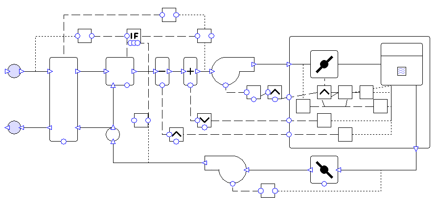
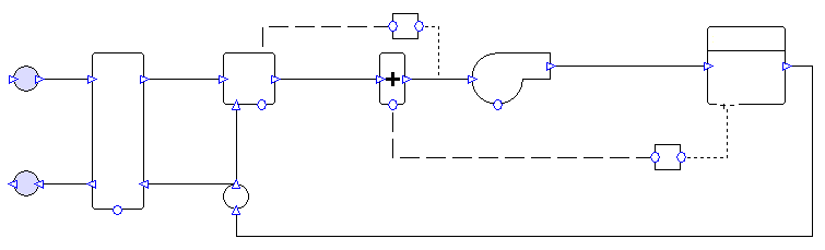
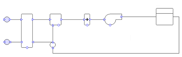
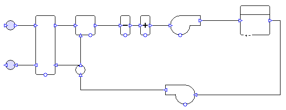
System 7 is shown below both with controllers, and with controllers hidden:

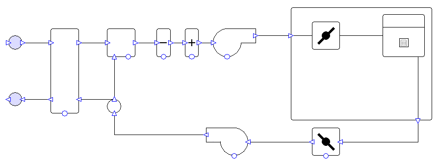
System Overview
These systems can have multiple zones sharing the same air handling unit.
Exchanger
By default, the system has a heat recovery unit with 50% enthalpy efficiency (50% sensible efficiency, 50% latent efficiency – enthalpy method). The exchanger is controlled to minimise the load on the coils.
The user should run the 90.1 Airside Efficiency Tool to determine whether or not the system will use an exchanger.
Mixing box
The system has an economiser controlled to reduce the load on the coils while providing at least the minimum fresh air requirement. When a specified temperature setpoint is reached the economiser is shut off and provides only the minimum requirement of fresh air. Outside of occupied hours, outside air is only brought into the system if doing so will reduce load on the coils.
Coils
The heating and cooling types are determined by the system type description in Appendix G (see compliance section for details). The system’s heating capacity is oversized by 25%, while the cooling capacity is oversized by 15%. It is possible to change these sizing fractions in the wizard.
The cooling coil is controlled to meet all the cooling demands in the attached zones. When the system is in cooling mode any heating requirements of the zones are met by radiators in the zone. The heating coil is controlled to operate only when all the attached zones have a heating demand. In any zones where warm air from the AHU is insufficient to meet the heating demand, the shortfall is made up by radiators in the zones.
The cooling coil setpoint temperature is controlled to increase by 5°F when the highest cooling signal from the grouped zones is less than 0.5. This is to satisfy the requirement for supply temperature reset under minimum cooling conditions. This control can be used as the basis for a more complex control, e.g., one linked to outside air temperature. It is recommended that whatever control is used, a cooling signal of 1 should always supply air at the lower temperature (i.e., at a delta T of 20°F) otherwise the system will produce unmet hours.
AHU Fans
AHU fans are variable volume. Fans are on a schedule set to run whenever any zones in the system have occupancy or a heating or cooling requirement. The maximum flow rate for the AHU fans is sized on a supply-air-to-room-temperature difference of 20°F (11.11°C).
The user should change the fan efficiency and pressure values from the values assigned by the wizard. The 90.1 Airside Efficiency Tool speeds up the process of calculating and assigning the correct values.
The fans are controlled to maintain a constant pressure while the dampers open and close to vary the airflow into each zone. The fan pressure is reset so that at least one zone damper must be almost completely open at all times.
Dampers
The dampers for each zone are controlled to permit the minimum air flow whenever the zone has occupancy or an AHU heating or cooling requirement. The dampers can open further when AHU cooling is required. The dampers can also open further when heating is required, but only if the AHU is supplying warm air; this is to avoid allowing in large amounts of cool air into a room that needs heating (as the AHU can be in cooling mode while some zones require heating, see “Coils” above).
Zone heating
Each zone has its own radiator which operates whenever heating is required and this demand has not been met by the AHU.
Compliance with 90.1 versions 2007, 2010, 2013, 2016, 2019, & 2022
Section 6.4.3.4.3 (2007), 6.4.3.4.2 (2010, 2013, 2016, 2019, & 2022): The wizard sets up the economiser so that outside of occupied hours outside air is only brought into the system if doing so would reduce the load on the coils. (To shut off outside air altogether in unoccupied hours, the user would change the economiser component “mode when off” property from “No Minimum” to “Recirc”.)
Section 6.4.3.9 (2007 & 2010), 6.4.3.8 (2013, 2016, 2019, & 2022): The user must decide whether demand control ventilation is required. The user can set up demand control ventilation by using one of the “hourly” methods on the zone fresh air rates.
Section 6.5.3.2.3: The wizard sets up the fan controls to reset the fan pressure so that at least one zone damper must be almost completely open at all times.
Section G3.1.1 (2007, 2010, 2013, 2016, & 2019), G3.2.1.2 & G3.2.1.3 (2022): The user can assign any number of zones to the same system. In most cases the user should create a separate system for each floor. Exceptions apply in some cases, and it is recommended that the user checks the list of exceptions in this section with particular care.
Table G3.1 part 4: The wizard sets up the AHU fans to run on hours when there is occupancy or a requirement (in the TSD) for heating or cooling. See also section G3.1.2.4 (2007, 2016, & 2019) or G3.1.2.5 (2010 & 2013).
Table G3.1.1.B (2007 & 2010), G3.1.1-4 (2013, 2016, 2019, & 2022): The wizard creates variable air volume systems with heating and cooling matching the types specified in the table.
Section G3.1.2.1 (2007, 2010, 2013, 2016, & 2019), G3.2.2.1 (2022): The user should run the 90.1 Plant Efficiency Tool to ensure that equipment efficiencies are set in accordance with the relevant sections or tables (depending on the 90.1 version selected in the tool).
Section G3.1.2.2 (2007, 2010, 2013, 2016, & 2019), G3.2.2.2 (2022): By default, the wizard sets heating equipment to oversize by 25% and cooling equipment to oversize by 15%.
Section G3.1.2.2.1 (2007, 2010, 2013, 2016, & 2019), G3.2.2.2.1 (2022): The user must ensure that equipment is being sized on an appropriate design condition. Design conditions can be assigned to equipment in the wizard.
Section G3.1.2.3 (2007), G3.1.2.4 (2010 & 2013): The user must determine whether a preheat coil is required and ensure that is controlled correctly. If a preheat coil is enabled in the wizard, it will have the same heating source as the rest of the heating for the selected system.
Section G3.1.2.4 (2007, 2016, & 2019), G3.1.2.5 (2010 & 2013): The wizard sets up the AHU fans to run on hours when there is occupancy or a requirement (in the TSD) for heating or cooling. If there are any health and safety requirements for minimum ventilation outside of occupied hours, the user should edit the system accordingly.
Section G3.1.2.5 (2007, 2016, & 2019), G3.1.2.6 (2010 & 2013), G3.2.2.4 (2022): The user must ensure that minimum outdoor air ventilation rates are the same in the proposed and baseline buildings. There is a tool in the Tas 90.1 studio to copy the zone fresh air rate values from the proposed TPD file to the baseline TPD files or vice versa.
Section G3.1.2.6 (2007, 2016, & 2019), G3.1.2.7 (2010 & 2013), G3.2.2.5 (2022): The wizard creates the system with an outdoor air economiser. Exceptions apply in some cases – the user should check these and if an economiser should not be included, then they can change the mixing box operation in the wizard to fresh air only.
Section G3.1.2.7 (2007, 2016, & 2019), G3.1.2.8 (2010 & 2013), G3.2.2.6 (2022): The wizard creates the economiser with high-limit shutoff control, the setpoint for which can be specified by the user in the wizard. The user must decide what setpoint is required (table G3.1.2.6B (2007 & 2010) or G3.1.2.8 (2013) or G3.1.2.7 (2016 & 2019) or G3.2.2.6 (2022)). The user has the option to deactivate the high-limit shutoff in the wizard.
Section G3.1.2.8 (2007, 2016, & 2019), G3.1.2.9 (2010 & 2013), G3.2.2.7 (2022): The wizard sizes the maximum flow rate for the AHU fans on a supply-air-to-room-temperature difference of 20°F (11.11°C). The wizard sets the coil setpoint values to match this temperature difference.
Section G3.1.2.9 (2007, 2016, & 2019), G3.1.2.10 (2010 & 2013), G3.2.2.8 (2022): The user should run the 90.1 Airside Efficiency Tool to assign the correct system fan power.
Section G3.1.2.10 (2007, 2016, & 2019), G3.1.2.11 (2010 & 2013), G3.2.2.9 (2022): By default, the wizard creates heat recovery with 50% enthalpy efficiency. The user should run the 90.1 Airside Efficiency Tool to determine whether or not the system should use a heat exchanger.
Section G3.1.3.12 (2007, 2010, 2013, 2016, & 2019), G3.2.3.12 (2022): By default, the wizard puts a control on the cooling supply temperature to reset it higher by 5°F when the largest cooling signal from the group is less than 0.5.
Section G3.1.3.13 (2007, 2010, 2013, 2016, & 2019), G3.2.3.13 (2022): By default, the wizard applies a minimum sizing fraction so that the zone minimum flow rate is at least 30% of the maximum flow rate. If there are special requirements for a zone then the user can change this fraction.
Section G3.1.3.15 (2007, 2010, 2013, 2016, & 2019), G3.2.3.15 (2022): The wizard sets up the fan part load performance to match method 1 specified in Table G3.1.3.15 (2007, 2010, 2013, 2016, & 2019) or Table G3.2.3.15 (2022).
Section G3.1.3.18 (2013, 2016, & 2019), G3.2.3.18 (2022): The user must determine whether dehumidification is required and that it is set up and controlled correctly.
Section G3.1.3.19 (2016 & 2019), G3.2.3.19 (2022): For systems 5 and 7 the user should add a preheat coil with a fixed setpoint 20°F (11.11°C) less than the room heating setpoint. The heating source should match the rest of the heating for the system.
Systems 6 and 8
Systems 6 and 8 are set up to match the requirements of 90.1 versions 2007, 2010, 2013, 2016, 2019, & 2022.
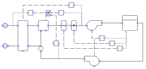
System 8 is shown below both with controllers, and with controllers hidden:

System Overview
These systems can have multiple zones sharing the same air handling unit.
Exchanger
By default, the system has a heat recovery unit with 50% enthalpy efficiency (50% sensible efficiency, 50% latent efficiency – enthalpy method). The exchanger is controlled to minimise the load on the coils.
The user should run the 90.1 Airside Efficiency Tool to determine whether or not the system will use an exchanger.
Mixing box
The system has an economiser controlled to reduce the load on the coils while providing at least the minimum fresh air requirement. When a specified temperature setpoint is reached the economiser is shut off and provides only the minimum requirement of fresh air. Outside of occupied hours, outside air is only brought into the system if doing so will reduce load on the coils.
Coils
The heating and cooling types are determined by the system type description in Appendix G (see compliance section for details). The system’s heating capacity is oversized by 25%, while the cooling capacity is oversized by 15%. It is possible to change these sizing fractions in the wizard.
The cooling coil is controlled to meet all the cooling demands in the attached zones. When the system is in cooling mode any heating requirements of the zones are met by PFP boxes local to the zones. The heating coil is controlled to operate only when all the attached zones have a heating demand. In any zones where warm air from the AHU is insufficient to meet the heating demand, the shortfall is made up by PFP boxes local to the zones.
The cooling coil setpoint temperature is controlled to increase by 5°F when the highest cooling signal from the grouped zones is less than 0.5. This is to satisfy the requirement for supply temperature reset under minimum cooling conditions. This control can be used as the basis for a more complex control, e.g., one linked to outside air temperature. It is recommended that whatever control is used, a cooling signal of 1 should always supply air at the lower temperature (i.e., at a delta T of 20°F) otherwise the system will produce unmet hours.
AHU Fans
AHU fans are variable volume. Fans are on a schedule set to run whenever any zones in the system have occupancy or a heating or cooling requirement. The maximum flow rate for the AHU fans is sized on a supply-air-to-room-temperature difference of 20°F (11.11°C).
The user should change the fan efficiency and pressure values from the values assigned by the wizard. The 90.1 Airside Efficiency Tool speeds up the process of calculating and assigning the correct values.
The fans are controlled to maintain a constant pressure while the dampers open and close to vary the airflow into each zone. The fan pressure is reset so that at least one zone damper must be almost completely open at all times.
Dampers
The dampers for each zone are controlled to permit the minimum air flow whenever the zone has occupancy or an AHU heating or cooling requirement. The dampers can open further when AHU cooling is required. The dampers can also open further when heating is required, but only if the AHU is supplying warm air; this is to avoid allowing in large amounts of cool air into a room that needs heating (as the AHU can be in cooling mode while some zones require heating, see “Coils” above).
PFP boxes
Each zone has a related PFP box with variable air flow. These provide heating whenever the zone has a heating demand which has not been met by the AHU.
Compliance with 90.1 versions 2007, 2010, 2013, 2016, 2019, & 2022
Section 6.4.3.4.3 (2007), 6.4.3.4.2 (2010, 2013, 2016, 2019, & 2022): The wizard sets up the economiser so that outside of occupied hours outside air is only brought into the system if doing so would reduce the load on the coils. (To shut off outside air altogether in unoccupied hours, the user would change the economiser component “mode when off” property from “No Minimum” to “Recirc”.)
Section 6.4.3.9 (2007 & 2010), 6.4.3.8 (2013, 2016, 2019, & 2022): The user must determine whether demand control ventilation is required. The user can set up demand control ventilation by using one of the “hourly” methods on the zone fresh air rates.
Section 6.5.3.2.3: The wizard sets up the fan controls to reset the fan pressure so that at least one zone damper must be almost completely open at all times.
Section G3.1.1 (2007, 2010, 2013, 2016, & 2019), G3.2.1.2 & G3.2.1.3 (2022): The user can assign any number of zones to the same system. In most cases the user should create a separate system for each floor. Exceptions apply in some cases, and it is recommended that the user checks the list of exceptions in this section with particular care.
Table G3.1 part 4: The wizard sets up the AHU fans to run on hours when there is occupancy or a requirement (in the TSD) for heating or cooling. See also section G3.1.2.4 (2007, 2016, & 2019) or G3.1.2.5 (2010 & 2013).
Table G3.1.1.B (2007 & 2010), G3.1.1-4 (2013, 2016, 2019, & 2022): The wizard creates variable air volume systems with heating and cooling matching the types specified in the table.
Section G3.1.2.1 (2007, 2010, 2013, 2016, & 2019), G3.2.2.1 (2022): The user should run the 90.1 Plant Efficiency Tool to ensure that equipment efficiencies are set in accordance with the relevant sections or tables (depending on the 90.1 version selected in the tool).
Section G3.1.2.2 (2007, 2010, 2013, 2016, & 2019), G3.2.2.2 (2022): By default, the wizard sets heating equipment to oversize by 25% and cooling equipment to oversize by 15%.
Section G3.1.2.2.1 (2007, 2010, 2013, 2016, & 2019), G3.2.2.2.1 (2022): The user must ensure that equipment is being sized on an appropriate design condition. Design conditions can be assigned to equipment in the wizard.
Section G3.1.2.3 (2007), G3.1.2.4 (2010 & 2013): The user must determine whether a preheat coil is required and ensure that is controlled correctly. If a preheat coil is enabled in the wizard, it will have the same heating source as the rest of the heating for the selected system.
Section G3.1.2.4 (2007, 2016, & 2019), G3.1.2.5 (2010 & 2013): The wizard sets up the AHU fans to run on hours when there is occupancy or a requirement (in the TSD) for heating or cooling. If there are any health and safety requirements for minimum ventilation outside of occupied hours, the user should edit the system accordingly.
Section G3.1.2.5 (2007, 2016, & 2019), G3.1.2.6 (2010 & 2013), G3.2.2.4 (2022): The user must ensure that minimum outdoor air ventilation rates are the same in the proposed and baseline buildings. There is a tool in the Tas 90.1 studio to copy the zone fresh air rate values from the proposed TPD file to the baseline TPD files or vice versa.
Section G3.1.2.6 (2007, 2016, & 2019), G3.1.2.7 (2010 & 2013), G3.2.2.5 (2022): The wizard creates the system with an outdoor air economiser. Exceptions apply in some cases – the user should check these and if an economiser should not be included, then they can change the mixing box operation in the wizard to fresh air only.
Section G3.1.2.7 (2007, 2016, & 2019), G3.1.2.8 (2010 & 2013), G3.2.2.6 (2022): The wizard creates the economiser with high-limit shutoff control, the setpoint for which can be specified by the user in the wizard. The user must decide what setpoint is required (table G3.1.2.6B (2007 & 2010) or G3.1.2.8 (2013) or G3.1.2.7 (2016 & 2019) or G3.2.2.6 (2022)). The user has the option to deactivate the high-limit shutoff in the wizard.
Section G3.1.2.8 (2007, 2016, & 2019), G3.1.2.9 (2010 & 2013), G3.2.2.7 (2022): The wizard sizes the maximum flow rate for the AHU fans on a supply-air-to-room-temperature difference of 20°F (11.11°C). The wizard sets the coil setpoint values to match this temperature difference.
Section G3.1.2.9 (2007, 2016, & 2019), G3.1.2.10 (2010 & 2013), G3.2.2.8 (2022): The user should run the 90.1 Airside Efficiency Tool to assign the correct system fan power.
Section G3.1.2.10 (2007, 2016, & 2019), G3.1.2.11 (2010 & 2013), G3.2.2.9 (2022): By default, the wizard creates heat recovery with 50% enthalpy efficiency. The user should run the 90.1 Airside Efficiency Tool to determine whether or not the system should use a heat exchanger.
Section G3.1.3.12 (2007, 2010, 2013, 2016, & 2019), G3.2.3.12 (2022): By default, the wizard puts a control on the cooling supply temperature to reset it higher by 5°F when the largest cooling signal from the group is less than 0.5.
Section G3.1.3.14 (2007, 2010, 2013, 2016, & 2019), G3.2.3.14 (2022): By default, the wizard sets up the maximum and minimum flow rates of the PFP boxes to be 0.5 and 0.3 of the maximum flow rate, respectively. If the minimum outdoor air ventilation requirement is larger than this minimum, the former should be used instead. If the user changes the way in which the fresh air rate is calculated, they should ensure that the PFP boxes are updated if necessary. The wizard sets the SFP of the PFP boxes to 0.35W/cfm (0.74W/l/s). The 90.1 Airside Efficiency Tool will reset the PFP box SFP to this value if the user changes it.
Section G3.1.3.15 (2007, 2010, 2013, 2016, & 2019), G3.2.3.15 (2022): The wizard sets up the fan part load performance to match method 1 specified in Table G3.1.3.15 (2007, 2010, 2013, 2016, & 2019) or Table G3.2.3.15 (2022).
Section G3.1.3.18 (2013, 2016, & 2019), G3.2.3.18 (2022): The user must determine whether dehumidification is required and that it is set up and controlled correctly.
Section G3.1.3.19 (2016 & 2019), G3.2.3.19 (2022): For systems 6 and 8 the user should add a preheat coil with a fixed setpoint 20°F (11.11°C) less than the room heating setpoint. The heating source should match the rest of the heating for the system.
Systems 9 and 10
Systems 9 and 10 are set up to match the requirements of 90.1 versions 2010, 2013, 2016, 2019, and 2022. These systems do not exist in 90.1-2007.
There are two versions of each system available in the systems wizard; multi-zone and single-zone versions. The multi-zone version is intended for use in projects using the 2010 version of 90.1.
System 9 (single-zone) is shown below both with controllers, and with controllers hidden:
System 9 (multi-zone) is shown below both with controllers, and with controllers hidden:
System Overview
The user can choose to create one system per zone or a system where multiple zones share the same air handling unit (90.1 version 2010).
Exchanger
By default, the system has a heat recovery unit with 50% enthalpy efficiency (50% sensible efficiency, 50% latent efficiency – enthalpy method). The exchanger has a setpoint of 105°F (40.56°C) in order to reduce the load on the heating coil, which has the same setpoint.
The user should run the 90.1 Airside Efficiency Tool to determine whether or not the system will use an exchanger.
Mixing box
The system has a mixing box which allows only the minimum rate of fresh air into the system.
Heating coil
The heating type is determined by the system type description in Appendix G (see compliance section for details). The coil is oversized by 25% - it is possible to change this sizing fraction in the wizard. The coil is controlled to meet the zone’s heating demands.
In the multi-zone system, the coil is controlled to operate only when all the attached zones have a heating demand. In any zones where warm air from the AHU is insufficient to meet the heating demand, the shortfall is made up by radiators in the zones.
Fan
Constant volume fan, set on a schedule to run whenever the zone has occupancy or a heating requirement. The flow rate is sized on the difference between the lower thermostat limit of the room and a supply temperature of 105°F (40.56°C).
The user should change the fan efficiency and pressure values from the values assigned by the wizard. The 90.1 Airside Efficiency Tool speeds up the process of calculating and assigning the correct values.
Compliance with 90.1 versions 2010, 2013, 2016, 2019, & 2022
Section G3.1.1 (2010, 2013, 2016, & 2019), G3.2.1.3 (2022):
Single-zone system: The wizard creates a separate system for each zone.
Multi-zone system (2010): The user can assign any number of zones to the same system. In most cases the user should create a separate system for each floor. Exceptions apply in some cases, and it is recommended that the user checks the list of exceptions in this section with particular care.
Table G3.1 part 4: The wizard sets up the fans to run on hours when there is occupancy or a requirement (in the TSD) for heating. See also section G3.1.2.4 (2016 & 2019) or G3.1.2.5 (2010 & 2013).
Table G3.1.1.B (2010), G3.1.1-4 (2013, 2016, 2019, & 2022): The wizard creates constant air volume systems with heating matching the type specified in the table.
Section G3.1.2.1 (2010, 2013, 2016, & 2019), G3.2.2.1 (2022): The user should run the 90.1 Plant Efficiency Tool to ensure that equipment efficiencies are set in accordance with the relevant sections or tables (depending on the 90.1 version selected in the tool).
Section G3.1.2.2 (2010, 2013, 2016, & 2019), G3.2.2.2 (2022): By default, the wizard sets heating equipment to oversize by 25%.
Section G3.1.2.2.1 (2010, 2013, 2016, & 2019), G3.2.2.2.1 (2022): The user must ensure that equipment is being sized on an appropriate design condition. Design conditions can be assigned to equipment in the wizard.
Section G3.1.2.4 (2010 & 2013): The user must determine whether a preheat coil is required and ensure that is controlled correctly. If a preheat coil is enabled in the wizard, it will have the same heating source as the rest of the heating for the selected system.
Section G3.1.2.4 (2016 & 2019), G3.1.2.5 (2010 & 2013): The wizard sets up the fan to run on hours when there is occupancy or a requirement (in the TSD) for heating. If there are any health and safety requirements for minimum ventilation outside of occupied hours, the user should edit the system accordingly.
Section G3.1.2.5 (2016 & 2019). G3.1.2.6 (2010 & 2013), G3.2.2.4 (2022): The user must ensure that minimum outdoor air ventilation rates are the same in the proposed and baseline buildings. There is a tool in the Tas 90.1 studio to copy the zone fresh air rate values from the proposed TPD file to the baseline TPD files or vice versa.
Section G3.1.2.6 (2016 & 2019), G3.1.2.7 (2010 & 2013), G3.2.2.5 (2022): The wizard creates systems 9 and 10 with a mixing box which allows only the minimum rate of fresh air into the system.
Section G3.1.2.8.2 (2016 & 2019), G3.1.2.9.2 (2010 & 2013), G3.2.2.7.2 (2022): The wizard sizes the flow rates on the difference between the lower thermostat limit of the room and a supply temperature of 105°F (40.56°C). The wizard sets the coil setpoint values to match this temperature difference.
Section G3.1.2.9 (2016 & 2019), G3.1.2.10 (2010 & 2013), G3.2.2.8 (2022): The user should run the 90.1 Airside Efficiency Tool to assign the correct system fan power.
Section G3.1.2.10 (2016 & 2019), G3.1.2.11 (2010 & 2013), G3.2.2.9 (2022): By default, the wizard creates heat recovery with 50% enthalpy efficiency. The user should run the 90.1 Airside Efficiency Tool to determine whether or not the system should use a heat exchanger.
System 11
System 11 is set up to match the requirements of 90.1 versions 2013, 2016, 2019, and 2022. This system does not exist in 90.1 versions 2007 or 2010.
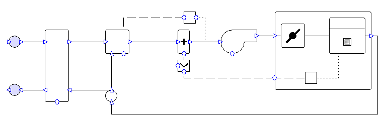
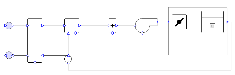
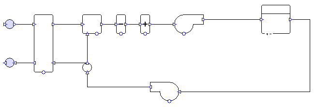
System 11 is shown below both with controllers, and with controllers hidden:
System Overview
One system is created per zone.
Exchanger
By default, the system has a heat recovery unit with 50% enthalpy efficiency (50% sensible efficiency, 50% latent efficiency – enthalpy method). The exchanger is controlled to minimise the load on the coils.
The user should run the 90.1 Airside Efficiency Tool to determine whether or not the system will use an exchanger.
Mixing box
The system has a mixing box which allows only the minimum rate of fresh air into the system.
Coils
The heating and cooling types are determined by the system type description in Appendix G (see compliance section for details). Note that system 11 may have electric heating or hot water heating, depending on the dominant heating source in the proposed building. By default, the wizard sets up system 11 with hot water heating. The system’s heating capacity is oversized by 25%, while the cooling capacity is oversized by 15%. It is possible to change these sizing fractions in the wizard. The coils are controlled to meet the zone’s heating and cooling demands.
Fans
Fans are variable volume. Fans run continuously for all hours of the year. The flow rates are sized on a supply-air-to-room-temperature difference of 20°F (11.11°C).
The user should change the fan efficiency and pressure values from the values assigned by the wizard. The 90.1 Airside Efficiency Tool speeds up the process of calculating and assigning the correct values.
Compliance with 90.1 version 2013, 2016, 2019, & 2022
Section G3.1.1 (2013, 2016, & 2019), G3.2.1.3 (2022): The wizard creates a separate system for each zone.
Table G3.1 part 4: As system 11 is intended for use with computer rooms, the wizard sets up the fans to run continuously throughout all hours of the year (exception 3).
Table G3.1.1-4: The wizard creates a variable air volume system with heating and cooling matching the types specified in the table. Note that by default system 11 is created using hot water heating, and if the heating type should be electric resistance, then the user should make this change manually after the system has been created with the wizard.
Section G3.1.2.1 (2013, 2016, & 2019), G3.2.2.1 (2022): The user should run the 90.1 Plant Efficiency Tool to ensure that equipment efficiencies are set in accordance with the relevant sections or tables (depending on the 90.1 version selected in the tool).
Section G3.1.2.2 (2013, 2016, & 2019), G3.2.2.2 (2022): By default, the wizard sets heating equipment to oversize by 25% and cooling equipment to oversize by 15%.
Section G3.1.2.2.1 (2013, 2016, & 2019), G3.2.2.2.1 (2022): The user must ensure that equipment is being sized on an appropriate design condition. Design conditions can be assigned to equipment in the wizard.
Section G3.1.2.4 (2013): The user must determine whether a preheat coil is required and ensure that is controlled correctly. If a preheat coil is enabled in the wizard, it will have the same heating source as the rest of the heating for the selected system.
Section G3.1.2.4 (2016 & 2019), G3.1.2.5 (2013): Rather than run the fans during occupancy or whenever there is a heating or cooling requirement, the fans are set up to run on every hour of the year, in accordance with exception 3 of Table G3.1 part 4.
Section G3.1.2.5 (2016 & 2019), G3.1.2.6 (2013), G3.2.2.4 (2022): The user must ensure that minimum outdoor air ventilation rates are the same in the proposed and baseline buildings. There is a tool in the Tas 90.1 studio to copy the zone fresh air rate values from the proposed TPD file to the baseline TPD files or vice versa.
Section G3.1.2.6 (2016 & 2019), G3.1.2.7 (2013), G3.2.2.5 (2022): As system 11 is intended for use with computer rooms, the wizard creates a mixing box which allows only the minimum rate of fresh air into the system (exception 3). The user can change the behaviour of the mixing box in the wizard, but this should not be necessary.
Section G3.1.2.6.1 (2016 & 2019), G3.1.2.7.1 (2013), G3.2.2.5.1 (2022): The wizard creates a water-side economiser for system 11, see plant section for more details.
Section G3.1.2.7 (2016 & 2019), G3.1.2.8 (2013), G3.2.2.6 (2022): If the user chooses economiser behaviour for the mixing box in the wizard (which is not expected – see note on Section G3.1.2.6 (2016 & 2019) or G3.1.2.7 (2013) or G3.2.2.5 (2022)), then the wizard creates the economiser with high-limit shutoff control, the setpoint for which can be specified by the user in the wizard. The user must decide what setpoint is required (Table G3.1.2.7 (2016 & 2019) or G3.1.2.8 (2013) or G3.2.2.6 (2022)).
Section G3.1.2.8.1 (2016 & 2019), G3.1.2.9.1 (2013), G3.2.2.7 (2022): The wizard sizes the flow rates on a supply-air-to-room-temperature difference of 20°F (11.11°C). The wizard sets the cooling coil setpoint value to match this temperature difference.
Section G3.1.2.9 (2016 & 2019), G3.1.2.10 (2013), G3.2.2.8 (2022): The user should run the 90.1 Airside Efficiency Tool to assign the correct system fan power.
Section G3.1.2.10 (2016 & 2019), G3.1.2.11 (2013), G3.2.2.9 (2022): By default, the wizard creates heat recovery with 50% enthalpy efficiency. The user should run the 90.1 Airside Efficiency Tool to determine whether or not the system should use a heat exchanger.
Section G3.1.3.12 (2019), G3.2.3.12 (2022): By default, there is no supply temperature reset for this system. For 90.1 versions 2019 & 2022, the user should activate this option in the wizard; this puts a control on the cooling supply temperature to reset it higher by 5°F when the largest cooling signal from the group is less than 0.5.
Section G3.1.3.17 (2013, 2016, & 2019), G3.2.3.17 (2022): The wizard sets up the component controls so that at cooling requirements less than 50% of the peak, supply airflow rate is held at 50% while the supply temperature changes, and at loads between 50% and 100%, the supply temperature is held constant while the airflow rate is varied to meet the cooling requirement. Note that depending on outside air conditions and the behaviour of the exchanger and mixing box, a room cooling requirement of 50% may not correspond to a cooling coil load of 50% of the peak sized value.
Section G3.1.3.18 (2016, & 2019), G3.2.3.18 (2022): The user must determine whether dehumidification is required and that it is set up and controlled correctly.
Systems 12 and 13
Systems 12 and 13 are set up to match the requirements of 90.1 versions 2013, 2016, 2019, & 2022. These systems do not exist in 90.1 versions 2007 or 2010.
System 12 is shown below both with controllers, and with controllers hidden:
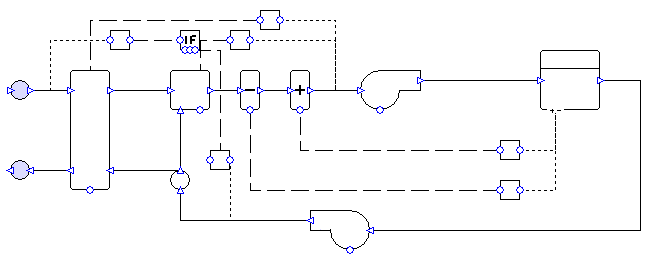
System Overview
One system is created per zone.
Exchanger
By default, the system has a heat recovery unit with 50% enthalpy efficiency (50% sensible efficiency, 50% latent efficiency – enthalpy method). The exchanger is controlled to minimise the load on the coils.
The user should run the 90.1 Airside Efficiency Tool to determine whether or not the system will use an exchanger.
Mixing box
Systems 12 and 13 have an economiser controlled to reduce the load on the coils while providing at least the minimum fresh air requirement. When a specified temperature setpoint is reached the economiser is shut off and provides only the minimum requirement of fresh air. Outside of occupied hours, outside air is only brought into the system if doing so will reduce load on the coils.
Coils
The heating and cooling types are determined by the system type description in Appendix G (see compliance section for details). The system’s heating capacity is oversized by 25%, while the cooling capacity is oversized by 15%. It is possible to change these sizing fractions in the wizard. The coils are controlled to meet the zone’s heating and cooling demands.
Fans
Fans are constant volume. Fans are on a schedule set to run whenever the zone has occupancy or a heating or cooling requirement. The flow rates are sized on a supply-air-to-room-temperature difference of 20°F (11.11°C).
The user should change the fan efficiency and pressure values from the values assigned by the wizard. The 90.1 Airside Efficiency Tool speeds up the process of calculating and assigning the correct values.
Compliance with 90.1 versions 2013, 2016, 2019, & 2022
Section 6.4.3.4.2: The wizard sets up the economiser so that outside of occupied hours outside air is only brought into the system if doing so would reduce the load on the coils. (To shut off outside air altogether in unoccupied hours, the user would change the economiser component “mode when off” property from “No Minimum” to “Recirc”.)
Section G3.1.1 (2013, 2016, & 2019), G3.2.1.3 (2022): The wizard creates a separate system for each zone.
Table G3.1 part 4: The wizard sets up the fans to run on hours when there is occupancy or a requirement (in the TSD) for heating or cooling. See also section G3.1.2.5 (2013) or G3.1.2.4 (2016 & 2019).
Table G3.1.1-4: The wizard creates constant air volume systems with heating and cooling matching the types specified in the table.
Section G3.1.2.1 (2013, 2016, & 2019), G3.2.2.1 (2022): The user should run the 90.1 Plant Efficiency Tool to ensure that equipment efficiencies are set in accordance with the relevant sections or tables (depending on the 90.1 version selected in the tool).
Section G3.1.2.2 (2013, 2016, & 2019), G3.2.2.2 (2022): By default, the wizard sets heating equipment to oversize by 25% and cooling equipment to oversize by 15%.
Section G3.1.2.2.1 (2013, 2016, & 2019), G3.2.2.2.1 (2022): The user must ensure that equipment is being sized on an appropriate design condition. Design conditions can be assigned to equipment in the wizard.
Section G3.1.2.4 (2013): The user must determine whether a preheat coil is required and ensure that is controlled correctly. If a preheat coil is enabled in the wizard, it will have the same heating source as the rest of the heating for the selected system.
Section G3.1.2.5 (2013), G3.1.2.4 (2016 & 2019): The wizard sets up the fans to run on hours when there is occupancy or a requirement (in the TSD) for heating or cooling. If there are any health and safety requirements for minimum ventilation outside of occupied hours, the user should edit the system accordingly.
Section G3.1.2.6 (2013), G3.1.2.5 (2016 & 2019), G3.2.2.4 (2022): The user must ensure that minimum outdoor air ventilation rates are the same in the proposed and baseline buildings. There is a tool in the Tas 90.1 studio to copy the zone fresh air rate values from the proposed TPD file to the baseline TPD files or vice versa.
Section G3.1.2.7 (2013), G3.1.2.6 (2016 & 2019), G3.2.2.5 (2022): The wizard creates systems 12 and 13 with an outdoor air economiser. Exceptions apply in some cases – the user should check these and if an economiser should not be included, then they can change the mixing box operation in the wizard to fresh air only.
Section G3.1.2.8 (2013), G3.1.2.7 (2016 & 2019), G3.2.2.6 (2022): The wizard creates the economiser for systems 12 and 13 with high-limit shutoff control, the setpoint for which can be specified by the user in the wizard. The user must decide what setpoint is required (Table G3.1.2.7 (2016 & 2019) or G3.1.2.8 (2013) or G3.2.2.6 (2022)). The user has the option to deactivate the high-limit shutoff in the wizard.
Section G3.1.2.9.1 (2013), G3.1.2.8.1 (2016 & 2019), G3.2.2.7 (2022): The wizard sizes the flow rates on a supply-air-to-room-temperature difference of 20°F (11.11°C). The wizard sets the coil setpoint values to match this temperature difference.
Section G3.1.2.10 (2013), G3.1.2.9 (2016 & 2019), G3.2.2.8 (2022): The user should run the 90.1 Airside Efficiency Tool to assign the correct system fan power.
Section G3.1.2.11 (2013), G3.1.2.10 (2016 & 2019), G3.2.2.9 (2022): By default, the wizard creates heat recovery with 50% enthalpy efficiency. The user should run the 90.1 Airside Efficiency Tool to determine whether or not the system should use a heat exchanger.
Section G3.1.3.18 (2013, 2016, & 2019), G3.2.3.18 (2022): The user must determine whether dehumidification is required and that it is set up and controlled correctly.
Section G3.1.3.19 (2016 & 2019), G3.2.3.19 (2022): For Systems 12 and 13 the user should not add a preheat coil to the system.
90.1 Airside Efficiency Tool
Use the 90.1 Airside Efficiency Tool to assign the correct fan power and heat exchanger efficiency to each baseline system.
Note that it is only necessary to run the tool once, as long as the system types and the options selected for the systems do not change. It is unnecessary to run the tool again if the air flow rates change. All the data required to calculate the correct fan SFP and exchanger efficiency will be written to the components when “Finish” is pressed. This means that once the tool has been run for one baseline building, the systems file can be reused for the other three buildings without the user having to run the tool again for each one.
For VAV systems, the tool will automatically correct damper pressure drops to ensure correct operation. For baseline systems 5 and 7, the tool will also adjust the minimum flow rate according to the 90.1 version selected for the system.
Fans
Fan powers are calculated in accordance with Section G3.1.2.9 (2007, 2016 & 2019), G3.1.2.10 (2010 & 2013), or G3.2.2.8 (2022).
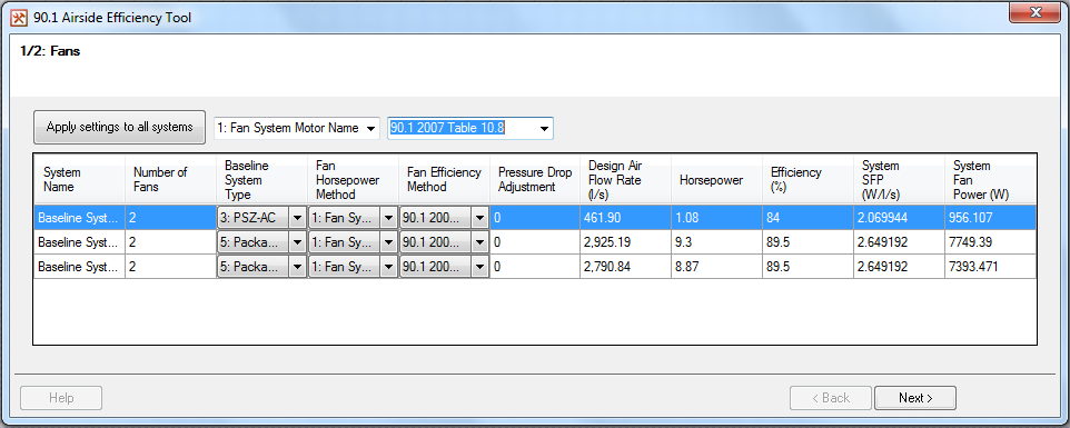
Number of Fans
Displays the number of fans detected for this system. If the system has an unexpected number of fans (e.g., because it has been edited or created without using the wizard), then the user may encounter an error message.
Baseline System Type
This will be detected automatically for systems created through the wizard. The system type determines the calculation method used for the fan power, and whether pressure drops around the system need to be changed (for VAV systems). Any systems left as type “None Selected” will be ignored when the new fan powers are applied. This is useful when the TPD contains a mixture of Baseline and non-Baseline type systems.
Fan Horsepower Method
As defined in Table 6.5.3.1.1A (2007 & 2010) or 6.5.3.1-1 (2013, 2016, 2019, & 2022) of the 90.1 document. To enter a user-calculated value for horsepower select “Enter Value”.
Fan Efficiency Method
The tool supports the fan efficiency methods from 90.1 versions 2007, 2010, 2013, 2016, 2019, and 2022. To enter a user-calculated value for fan efficiency select “Enter Value”.
Design Air Flow Rate
If the air flow rates haven’t been sized then zero will be shown for each system. Note that it is not necessary to complete a sizing run before pressing “Next” unless the “Enter Value” method is used for either fan horsepower or fan efficiency.
Hovering the cursor over the heading of most of the columns will display a tooltip giving a reference to the 90.1 document. Column widths can be adjusted as required.
Pressing “Next” will take the user to the page relating to Exchangers (see next section).
At the top of the window the user has the option to set the fan horsepower method and/or fan efficiency method for all the systems at once. Once the selections have been made in the drop-down boxes, press “Apply settings to all systems” to apply the selections to all systems in the grid below.
Leaving either option as “None Selected” means that some system settings will not be overwritten – for example if at the top of the window “None Selected” is chosen as the horsepower method and “90.1 2007 Table 10.8” is chosen as the fan efficiency method, then when “Apply settings to all systems” is pressed each system’s fan efficiency method will change to “90.1 2007 Table 10.8” but the horsepower method will not be changed.
On pressing “Apply settings to all systems”, the user will have the option to apply the selected regulation version (i.e., 2007, 2010, 2013, 2016, 2019, or 2022) to all the airside heat exchangers (see below).
Exchangers
Here it is determined whether or not each system should use a heat exchanger. This will depend upon the flow rates of the systems and whether any special exceptions apply, in accordance with Section G3.1.2.10 (2007, 2016, & 2019), G3.1.2.11 (2010 & 2013), or G3.2.2.9 (2022).
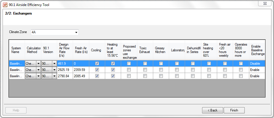
Calculation Method
The user can choose to manually enable or disable the exchanger for the selected system. In most instances “check against regulations” should be selected, which means that the tool will check the flow rates and exceptions to determine whether the exchanger should be used.
Design Air Flow Rate, Fresh Air Flow Rate
If the air flow rates haven’t been sized then zero will be shown for each system. Note that it is not necessary to complete a sizing run before pressing “Apply”.
As with the page related to fans, hovering over most column headings will display a tooltip giving more information, and column widths can be adjusted manually.
Pressing “Back” will return the user to the page relating to fans.
Pressing “Finish” will attempt to enter the values into the systems components (both fans and exchangers). If there are any problems with the inputs then the user will usually have the chance to save their changes without applying them, giving an opportunity to resolve the issue without losing work.