Waterside Systems
The setups of the waterside systems created by the Systems wizard are explained in this section. Systems can be set up to comply with 90.1 versions 2007, 2010, 2013, 2016, 2019, or 2022. For each system type there is an explanation of how the system complies with the 90.1 guidance. Points in bold are things that the user must check for themselves and enter data accordingly – compliance with the other points is either dealt with by the system setup itself as created by the wizard, or by running the 90.1 Plant Efficiency Tool.
Details of Baseline Waterside Systems
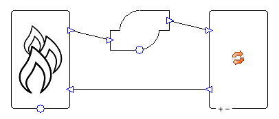
Fossil Fuel Boiler
System Overview
This system provides hot water for the baseline airside systems 1, 5, 7, 11, and 12.
Boiler
The boiler has a heating setpoint of 180°F (82.22°C), which is reset depending on the external dry-bulb temperature. The boiler is oversized by 25%. Note that although the airside heating equipment is also oversized by 25% this is not double-counting; the oversizing on the airside does not have a direct effect on the waterside sizing run.
Pump
The wizard creates a constant speed pump that runs continuously. The pressure drop in the heating collection varies depending on heating demand, varying the water flow rate. The pump is sized on a delta T of 50°F (27.78°C).
Compliance with 90.1 versions 2007, 2010, 2013, 2016, 2019, & 2022
Table 6.8.1.F (2007 & 2010), 6.8.1.6 (2013): The user should run the 90.1 Plant Efficiency Tool to ensure that the efficiency of the boiler is set correctly.
Section G3.1.2.1 (2007, 2010, 2013, 2016, 2019), G3.2.2.1 (2022): The user should run the plant efficiency tool to ensure that the efficiency of the boiler is set correctly.
Section G3.1.2.2 (2007, 2010, 2013, 2016, 2019), G3.2.2.2 (2022): By default, the wizard oversizes the boiler capacity by 25%.
Section G3.1.2.2.1 (2007, 2010, 2013, 2016, 2019), G3.2.2.2.1 (2022): The user must ensure that equipment is being sized on an appropriate design condition. Design conditions can be assigned to equipment in the wizard.
Section G3.1.3.2 (2007, 2010, 2013, 2016, 2019), G3.2.3.2 (2022): The user should ensure that the correct fuel is in use. The 90.1 Plant Efficiency Tool will calculate the appropriate number of boilers and set the boiler efficiency accordingly.
Section G3.1.3.3 (2007, 2010, 2013, 2016, 2019), G3.2.3.3 (2022): The wizard sets the boiler’s heating setpoint to 180°F (82.22°C), with a target return temperature of 130°F (54.44°C).
Section G3.1.3.4 (2007, 2010, 2013, 2016, 2019), G3.2.3.4 (2022): The wizard sets up the boiler setpoint so that it resets to 150°F (65.56°C) when the external dry-bulb temperature is 50°F (10°C) and above. When the external dry-bulb temperature is 20°F (-6.67°C) and below, the boiler setpoint is 180°F (82.22°C). When the dry-bulb temperature is between these two values, the boiler setpoint varies linearly between the two setpoint values.
Section G3.1.3.5 (2007, 2010, 2013, 2016, 2019), G3.2.3.5 (2022): The wizard sets the pressures around the system so that the pump consumption at full load will be 19W/gpm (301 W/l/s). By default, the pressure drop in the system is split 50-50 between the boiler and the heating collection. By default, the pump peak pressure is set to be 20% greater than the sum of the boiler and heating collection pressure drops. The pump is set up to run continuously and to ride the pump curve at part load. The user should check whether the system serves a floor area of over 120,000 ft2, and if so, then they should change the pump operation to variable speed (“Control Type” to “Variable Speed” in the pump properties).
Section G3.1.3.6 (2007, 2010, 2013, 2016, 2019), G3.2.3.6 (2022): The wizard sets the distribution efficiency of the heating collection to 100%. This eliminates all pipe losses.
Table G3.5.6 (2016, 2019, 2022): The user should run the 90.1 Plant Efficiency Tool to ensure that the efficiency of the boiler is set correctly.
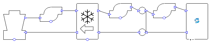
Chiller and Cooling Tower
System Overview
This system provides chilled water for the baseline airside systems 7, 8, 12, and 13.
Chiller pumps
The wizard creates a primary/secondary pumping system with constant speed pumps that run continuously. The pressure drop in the cooling collection varies depending on demand, varying the water flow rate in the secondary loop. The pumps are sized on a delta T of 6.67°C (12°F).
Chiller
This is a water-source chiller which transfers heat from the loop connected to the cooling collection (right hand side in image above) to the loop connected to the cooling tower (left hand side in image above).
The chiller has a cooling setpoint of 44°F (6.67°C), which is reset depending on the external dry-bulb temperature. The chiller is oversized by 15%. Note that although the airside cooling equipment is also oversized by 15% this is not double-counting; the oversizing on the airside does not have a direct effect on the waterside sizing run.
By default, the chiller has a motor efficiency of 85%, meaning that 85% of the chiller consumption is added as heat to the heat rejection loop (see components guide for details). The user can change this figure.
Cooling tower pump
The wizard creates a constant speed pump that runs continuously. The pump is sized on a delta T of 5.56°C (10°F).
Cooling tower
The cooling tower is set up to meet the peak cooling demand (found during the TPD sizing run) at the design conditions specified in the wizard. The cooling tower has two-speed fans (for 90.1 versions 2007 and 2010) or variable speed fans (for 90.1 versions 2013, 2016, 2019, and 2022). The minimum air flow rate is equal to two thirds of the maximum flow rate.
The fan flow rate used changes to meet the cooling load for each hour. For 90.1 versions 2007 and 2010, at high part loads the fans are cycled between the maximum and minimum fan speeds, and at low part loads the fans are cycled on and off at the minimum flow rate. For 90.1 versions 2013, 2016, 2019, and 2022, at high part loads the fan speed can vary between the maximum and minimum fan speeds (meaning a better fan efficiency than cycling between two speeds), and at low part loads the fan cycles on and off at the minimum flow rate.
The wizard sets up the fans to have a minimum efficiency of 38.2 gpm of water per fan hp (max fan load 310 W per l/s of water). It does this by limiting the fan load to 1,000 times the water flow rate, and making the fan SFP 0.31W per l/s of air. This means that the maximum possible fan load per l/s of water is 310W (0.31W/l/s multiplied by 1,000 l/s of water). These are the figures for 90.1 versions 2007 and 2010. For 90.1 versions 2013, 2016, 2019, and 2022 the values are 40.2 gpm of water per fan hp, 294W max fan load per l/s of water, and an SFP of 0.294W/l/s of air.
Compliance with 90.1 versions 2007, 2010, 2013, 2016, 2019, & 2022
Section 6.5.5.2: If the user selects 90.1 versions 2007, 2010, or 2013 in the wizard then the minimum air flow sizing ratio of the tower will be set to ensure the minimum air flow rate will be two thirds of the maximum air flow rate. If the user selects 90.1 versions 2016, 2019, or 2022 in the wizard then the minimum air flow sizing ratio is set to be one half of the maximum air flow rate. For versions 2007 and 2010 the user should determine whether the tower should have variable-speed fans (this is best done after a sizing run), and if necessary, make this change manually in the cooling tower properties. If versions 2013, 2016, or 2019 are selected in the wizard the tower will have variable speed fans.
Table 6.8.1.C (2007 & 2010), 6.8.1-3 (2013 & 2016): The user should run the 90.1 Plant Efficiency Tool to ensure that the efficiency of the chiller is set correctly.
Table 6.8.1.G (2007 & 2010), 6.8.1-7 (2013, 2016, 2019, & 2022): For versions 2007 and 2010 the wizard sets up the fans to have a minimum efficiency of 38.2 gpm of water per fan hp (max fan load 310 W per l/s of water). For versions 2013, 2016, 2019, & 2022, the fan efficiency is 40.2 gpm of water per fan hp (max fan load of 294 W per l/s of water).
Section G3.1.2.1 (2007, 2010, 2013, 2016 & 2019), Section G3.2.2.1 (2022): The user should run the plant efficiency tool to ensure that the efficiency of the chiller is set correctly.
Section G3.1.2.2 (2007, 2010, 2013, 2016 & 2019), Section G3.2.2.2 (2022): By default, the wizard oversizes the chiller capacity by 15%.
Section G3.1.2.2.1 (2007, 2010, 2013, 2016 & 2019), Section G3.2.2.2.1 (2022): The user must ensure that equipment is being sized on an appropriate design condition. Design conditions can be assigned to equipment in the wizard.
Section G3.1.3.6 (2007, 2010, 2013, 2016, & 2019), Section G3.2.3.6 (2022): The wizard sets the distribution efficiency of the cooling collection to 100%. This eliminates all pipe losses.
Section G3.1.3.7 (2007, 2010, 2013, 2016, & 2019), Section G3.2.3.7 (2022): The user should ensure that they assign an electric fuel source to the chiller in the wizard. The 90.1 Plant Efficiency Tool will calculate the appropriate number of chillers and set the chiller efficiency accordingly.
Section G3.1.3.8 (2007, 2010, 2013, 2016, & 2019), Section G3.2.3.8 (2022): The wizard sets the chiller’s cooling setpoint to 44°F (6.67°C), with a target return temperature of 56°F (13.33°C).
Section G3.1.3.9 (2007, 2010, 2013, 2016, & 2019), Section G3.2.3.9 (2022): The wizard sets up the chiller setpoint so that it resets to 54°F (12.22°C) when the external dry-bulb temperature is 60°F (15.56°C) and below. When the external dry-bulb temperature is 80°F (26.67°C) and above, the chiller setpoint is 44°F (6.67°C). When the dry-bulb temperature is between these two values, the chiller setpoint varies linearly between the two setpoint values.
Section G3.1.3.10 (2007, 2010, 2013, 2016, & 2019), Section G3.2.3.10 (2022): The wizard sets the pressures around the cooling collection loop so that the pump consumption at full load will be 22W/gpm (348.7 W/l/s). By default, the pressure drop is split so that 9W/gpm of this consumption is in the primary loop and 13W/gpm is in the secondary loop (values taken from 90.1 versions 2016, 2019, and 2022). By default, the pump peak pressures are set to be 20% greater than the pressure drops in their loops. The pumps are set up to run continuously, and the secondary pump is set up to ride the pump curve at part load. The user should check whether the cooling capacity of the system is over 300 tons, and if so, then they should change the secondary pump operation to variable speed (“Control Type” to “Variable Speed” in the pump properties).
Section G3.1.3.11 (2007, 2010, 2013, 2016, & 2019), Section G3.2.3.11 (2022): The wizard sets the pressures around the heat rejection loop so that the pump load will be 19W/gpm (301 W/l/s). The wizard sets up the tower to control to 70°F, which it will always try its best to reach (whether it can or not will depend on weather conditions). The wizard sets up the tower to have a design range of 10°F.
For versions 2007 and 2010, the tower is set up to have a design approach of 10°F – by default the design conditions match the rating condition from Table 6.8.1C.
For version 2013, 2016, and 2019, by default the tower is set up to exceed the rating condition from Table 6.8.1-7 – using the design approach formula from Section G3.1.3.11 the tower can achieve a lower approach (i.e., better cooling performance) than 10°F at the conditions listed in 6.8.1-7.
For versions 2016 and 2019 the user should check Table G3.1.3.11 and if appropriate change the setpoint from the default value of 70°F.
For version 2022, by default the tower is set up to exceed the rating condition from Table 6.8.1-7 – using the design approach formula from Section G3.2.3.11 the tower can achieve a lower approach (i.e., better cooling performance) than 10°F at the conditions listed in 6.8.1-7.
For versions 2022 the user should check Table G3.2.3.11 and if appropriate change the setpoint from the default value of 70°F.
90.1 Version |
SIM Setpoint |
DES WB |
DES Approach |
DES LWT |
DES Range |
DES EWT |
|---|---|---|---|---|---|---|
2007 |
70 |
75 |
10 |
85 |
10 |
95 |
2010 |
70 |
75 |
10 |
85 |
10 |
95 |
2013 |
70 |
75 |
7.72 (a) |
82.72 |
10 |
92.72 |
2016 |
70 (b) |
75 |
7.72 (a) |
82.72 |
10 |
92.72 |
2019 |
70 (b) |
75 |
7.72 (a) |
82.72 |
10 |
92.72 |
2022 |
70 (c) |
75 |
7.72 (d) |
82.72 |
10 |
92.72 |
All temperatures in °F
DES: Design. EWT: Entering Water Temperature. LWT: Leaving Water Temperature. SIM: Simulation. WB: Wetbulb.
This value is obtained from the design approach formula from section G3.1.3.11 with a wetbulb value of 75.
This value is 70°F by default but the user should check Table G3.1.3.11 and apply a different value if appropriate.
This value is 70°F by default but the user should check Table 12.5.2-4 and apply a different value if appropriate.
This value is obtained from the design approach formula from section G3.2.3.11 with a wetbulb value of 75.
Table G3.5.3 (2019 & 2022): The user should run the 90.1 Plant Efficiency Tool to ensure that the efficiency of the chiller is set correctly.
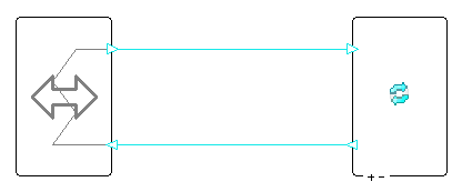
Chiller and Cooling Tower with Economiser

System Overview
This system provides chilled water for baseline airside system 11 in 90.1 versions 2013, 2016, 2019, and 2022. It is never used with systems from 90.1 versions 2007 or 2010.
Chiller pumps
The wizard creates a primary/secondary pumping system with constant speed pumps that run continuously. The pressure drop in the cooling collection varies depending on demand, varying the water flow rate in the secondary loop. The pumps are sized on a delta T of 6.67°C (12°F).
Chiller
This is a water-source chiller which transfers heat from the loop connected to the cooling collection (right hand side in image above) to the loop connected to the cooling tower (left hand side in image above).
The chiller has a cooling setpoint of 44°F (6.67°C). The chiller is oversized by 15%. Note that although the airside cooling equipment is also oversized by 15% this is not double-counting; the oversizing on the airside does not have a direct effect on the waterside sizing run.
By default, the chiller has a motor efficiency of 85%, meaning that 85% of the chiller consumption is added as heat to the heat rejection loop (see components guide for details). The user can change this figure.
Economiser
The economiser is built into the chiller component. The economiser allows the chiller to take advantage of free cooling whenever the water temperature leaving the cooling tower is lower than the return temperature from the cooling collection.
If the water temperature leaving the cooling tower is equal to or lower than the chiller setpoint, the chiller does not have to run and 100% of the load is met through the economiser. If the water temperature leaving the cooling tower is between the chiller setpoint and the return temperature from the cooling collection, then part of the load can be met through the economiser, reducing the demand on the chiller. If the temperature leaving the cooling tower is higher than the return temperature from the cooling collection, then the economiser is not used.
Cooling tower pump
The wizard creates a constant speed pump that runs continuously. The pump is sized on a delta T of 5.56°C (10°F).
Cooling tower
The cooling tower is set up to meet the peak cooling demand (found during the TPD sizing run) at the design conditions specified in the wizard. The cooling tower has variable speed fans. The minimum air flow rate is equal to two thirds of the maximum flow rate.
The fan flow rate used changes to meet the cooling load for each hour. At high part loads the fan speed can vary between the maximum and minimum fan speeds, and at low part loads the fan cycles on and off at the minimum flow rate.
The wizard sets up the fans to have a minimum efficiency of 40.2 gpm of water per fan hp (max fan load 294 W per l/s of water). It does this by limiting the fan load to 1,000 times the water flow rate, and making the fan SFP 0.294W per l/s of air. This means that the maximum possible fan load per l/s of water is 294W (0.294W/l/s multiplied by 1,000 l/s of water).
Compliance with 90.1 versions 2013, 2016, 2019 & 2022
Section 6.5.1.2.1: It is recommended that the user selects appropriate design conditions for the cooling tower from Table 6.5.1.2.1 and enters these into the wizard. Bear in mind that in order for the economiser to provide 100% of the cooling at these conditions, the tower must be able to meet the chiller setpoint.
Section 6.5.5.2: The wizard sets the minimum air flow sizing ratio of the tower to ensure the minimum air flow rate will be two thirds of the maximum air flow rate when 90.1-2013 is selected in the wizard, and one half of the maximum air flow rate when 90.1 version 2016, 2019, or 2022 is selected in the wizard.
Table 6.8.1-3 (2013 & 2016): The user should run the 90.1 Plant Efficiency Tool to ensure that the efficiency of the chiller is set correctly.
Table 6.8.1-7: The wizard sets up the fans to have a minimum efficiency of 40.2 gpm of water per fan hp (max fan load 294 W per l/s of water).
Section G3.1.2.1 (2013, 2016, & 2019), Section G3.2.2.1 (2022): The user should run the plant efficiency tool to ensure that the efficiency of the chiller is set correctly.
Section G3.1.2.2 (2013, 2016, & 2019), Section G3.2.2.2 (2022): By default, the wizard oversizes the chiller capacity by 15%.
Section G3.1.2.2.1 (2013, 2016, & 2019), Section G3.2.2.2.1 (2022): The user must ensure that equipment is being sized on an appropriate design condition. Design conditions can be assigned to equipment in the wizard.
Section G3.1.2.6.1 (2016 & 2019), G3.1.2.7.1 (2013), G3.2.2.5.1 (2022): The wizard sets up the cooling plant for system 11 with an integrated water side economiser (operation discussed above in “Economiser” section).
Section G3.1.3.6 (2013, 2016, & 2019), Section G3.2.3.6 (2022): The wizard sets the distribution efficiency of the cooling collection to 100%. This eliminates all pipe losses.
Section G3.1.3.7 (2013, 2016, & 2019), Section G3.2.3.7 (2022): The user should ensure that they assign an electric fuel source to the chiller in the wizard. The 90.1 Plant Efficiency Tool will calculate the appropriate number of chillers and set the chiller efficiency accordingly.
Section G3.1.3.8 (2013, 2016, & 2019), Section G3.2.3.8 (2022): The wizard sets the chiller’s cooling setpoint to 44°F (6.67°C), with a target return temperature of 56°F (13.33°C).
Section G3.1.3.10 (2013, 2016, & 2019), Section G3.2.3.10 (2022): The wizard sets the pressure drops around the system so that the full load pump consumption in the primary loop is 15W/gpm for 90.1-2013 systems and 12W/gpm for 90.1 version 2016 or 2019 systems, and so that the full load pump consumption in the secondary loop is 13W/gpm. By default, the pump peak pressures are set to be 20% greater than the pressure drops in their loops. The pumps are set up to run continuously, and the secondary pump is set up to ride the pump curve at part load. The user should check whether the cooling capacity of the system is over 300 tons, and if so, then they should change the secondary pump operation to variable speed (“Control Type” to “Variable Speed” in the pump properties).
Section G.3.1.3.11 (2013, 2016, & 2019), Section G3.2.3.11 (2022): The wizard sets the pressures around the heat rejection loop so that the pump load will be 24W/gpm for 90.1-2013, 22W/gpm for 90.1 versions 2016 and 2019. By default, the pump peak pressure is set to be 20% greater than the total pressure drop in the heat rejection loop. Rather than aim for the 70°F (or other value, if using 90.1 version 2016 or 2019) specified here, the wizard sets up the tower to control to the chiller’s setpoint of 44°F, which it will always try its best to reach (whether it can or not will depend on weather conditions). This is so that the economiser can meet 100% of the cooling load at the conditions required in section 6.5.1.2.1. The wizard sets up the tower to have a design range of 10°F.
Table G3.5.3 (2019 & 2022): The user should run the 90.1 Plant Efficiency Tool to ensure that the efficiency of the chiller is set correctly.
Air-Source Heat Pump
System Overview
This system represents the outdoor unit(s) of the heat pumps serving the following baseline systems: * Systems 1 and 3: One cooling coil per zone. * Systems 2 and 4: One cooling coil per zone, one heating coil per zone. * Systems 5 and 6: One cooling coil per air handling unit.
Air Source Heat Pump:
The component has the type “Single Split System”. This means that the component can represent multiple outdoor units – one outdoor unit is modelled for each indoor unit in the refrigerant group, i.e., for each DX coil component in the air side system(s).
The other important properties of the component are set using the 90.1 Plant Efficiency Tool.
By default, the classifications below are used for the heat pumps. These classifications affect the efficiencies calculated by the 90.1 Plant Efficiency Tool (and the classifications can be changed in that tool). * System 1: Packaged Terminal Air Conditioner * System 2: Packaged Terminal Heat Pump * System 3: Rooftop Air Conditioner * Systems 4, 5, and 6: Rooftop Heat Pump
Compliance with 90.1 versions 2007, 2010, 2013, 2016, 2019, & 2022
Tables 6.8.1.x (2007, 2010, 2013 & 2016): The user should run the 90.1 Plant Efficiency Tool to ensure that the efficiency of the heat pump is set correctly.
Section G3.1.2.1 (2007, 2010, 2013, 2016, & 2019), G3.2.2.1 (2022): The user should run the plant efficiency tool to ensure that the efficiency of the heat pump component is set correctly.
Section G3.1.2.2 (2007, 2010, 2013, 2016, & 2019), G3.2.2.2 (2022): By default, the wizard sets the heat pump heating capacity to oversize by 25% and heat pump cooling capacity to oversize by 15%.
90.1 Plant Efficiency Tool
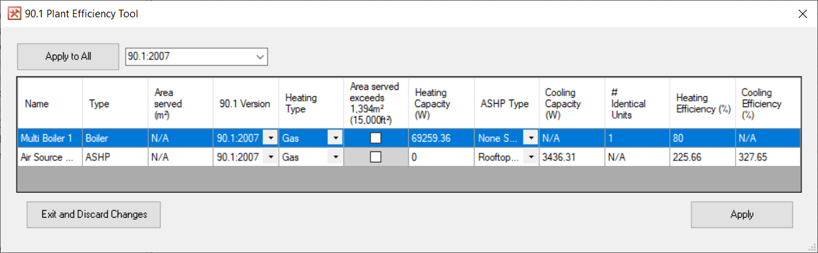
Use the 90.1 Plant Efficiency Tool to assign the correct heating and cooling efficiencies to the boilers, chillers, and heat pumps in the systems file.
Note it is only necessary to run the tool once, as long as the options selected for the components do not change. It is unnecessary to run the tool again if the heating or cooling capacities change. All the data required to calculate the correct efficiencies will be written to the components when “Apply” is pressed. This means that once the tool has been run for one baseline building, the systems file can be reused for the other three buildings without the user having to run the tool again for each one.
90.1 Version
For components where you do not want to use this tool to determine the efficiency, the 90.1 version should be “None Selected”. This component will then be ignored by the tool.
At the top of the window the user has the option to set the 90.1 version for all the components at once. Once the selection has been made in the drop-down box, press “Apply to all” to apply the selection to all components in the grid below.
Heating Type
This only applies to boilers and heat pumps.
Area Served
Only applies to boilers. This column only shows a value when the plantroom has been sized (as this process checks that the systems and plantroom circuits are valid). The tickbox is operated manually. Ticking the box effectively divides the heating capacity between two equally sized boilers (e.g., 500,000 Btu/h is divided between two and the component is sized as if its capacity is 250,000 Btu/h).
Heating Capacity, Cooling Capacity:
If the plant room hasn’t been sized then zero will be shown for each system. Note that it is not necessary to complete a sizing run before pressing “Apply”.
ASHP Type
Only applies to heat pumps. The type selected changes which tables are used to find efficiency values (see below Heating Efficiency and Cooling Efficiency sections below).
# Identical Units:
This only applies to boilers and chillers. Displays the number of identical boilers or chillers represented by the single component, depending on floor area served (for boilers) or cooling capacity (for chillers).
Heating Efficiency:
Boiler efficiencies are taken from Table 6.8.1.F (2007 & 2010) or Table 6.8.1.6 (2013) or Table G3.5.6 (2016, 2019, & 2022).
Heat pump heating efficiencies are taken from the tables shown below.
90.1 Version |
PTHP |
Rooftop HP |
|---|---|---|
2007 |
6.8.1D |
6.8.1B |
2010 |
6.8.1D |
6.8.1B |
2013 |
6.1.1-4 |
6.8.1-2 |
2016 |
6.1.1-4 |
6.8.1-2 |
2019 |
G3.5.4 |
G3.5.2 |
2022 |
G3.5.4 |
G3.5.2 |
Where necessary the equations given in Section G3.1.2.1 (90.1 versions 2007-2019) or G3.2.2.1 (90.1 2022) are used to convert the values given in the table into a heating COP figure.
The plant efficiency tool will also set up backup electric heating for heat pumps, in accordance with Section G3.1.3.1 (90.1 versions 2007-2019) or G3.2.3.1 (90.1 2022). It does this by changing the heating efficiency to 1.0 when the outdoor air temperature drops below 40°F (4.44°C).
Cooling Efficiency:
Chiller efficiencies are taken from Table 6.8.1.C (2007 & 2010) or Table 6.8.1-3 (2013 & 2016) or Table G3.5.3 (2019 & 2022).
Heat pump cooling efficiencies are taken from the tables shown below.
90.1 Version |
PTHP |
PTAC |
Rooftop HP |
Rooftop AC |
|---|---|---|---|---|
2007 |
6.8.1D |
6.8.1D |
6.8.1B |
6.8.1A |
2010 |
6.8.1D |
6.8.1D |
6.8.1B |
6.8.1A |
2013 |
6.1.1-4 |
6.1.1-4 |
6.8.1-2 |
6.8.1-1 |
2016 |
6.1.1-4 |
6.1.1-4 |
6.8.1-2 |
6.8.1-1 |
2019 |
G3.5.4 |
G3.5.4 |
G3.5.2 |
G3.5.1 |
2022 |
G3.5.4 |
G3.5.4 |
G3.5.2 |
G3.5.1 |
Where necessary, the equations given in Section G3.1.2.1 (90.1 versions 2007-2019) or G3.2.2.1 (90.1 2022) are used to convert the values given in tables into a cooling COP figure.
Where necessary SEER values are converted into EER values using
EER = (-0.02*SEER^2) + (1.12*SEER)
Where plant equipment efficiencies depend on the date (versions 2007, 2010, and 2013), a date of 1st August 2021 is assumed.