Setup Zones for the Heating Design Day
Video 2: The Setup Zones for the Heating Design Day page.
The Setup Zones for the Heating Design Day page will only appear if the user checked the Create a Heating Design Day option on the Select Design Day Type page. This page is used to setup the conditions for the steady state calculation.
The majority of the page is taken up by two tree views. The one on the left, called Available Zones, lists all zones in the TBD file (except external zones) that have not currently been setup. The tree view on the right, called Zones to be Sized, lists all zones that will be sized on the steady state calculation. Zones can be dragged across from one tree view to the other, as seen in Video 2.
When setting up a steady state calculation the zone’s: design dry bulb temperature, infiltration rate, ventilation rate, size factor and radiant proportion of the heating emitter all need to be provided. These are set using the values in the Zone Selection box. When you drag a zone onto the Zones to be Sized tree view, the currently entered values in this box are applied to the zone. The data can also be changed by selecting the zones in the tree view, amending the data in the Zone Selection Box and pressing the Set button.
The fields in the Zone Selection box are:
Zone Temperature – This field sets the design dry bulb temperature for the zone. This can be set in °C or °F, depending on the unit system Tas is using.
Infiltration – This field sets the infiltration rate for the zone. The unit used is air changes per hour. Please note that the infiltration rate cannot be negative.
Ventilation – This field sets the ventilation rate for the zone. The unit used is air changes per hour. Please note that the ventilation rate cannot be negative.
Size Factor – The Size Factor field allows you to oversize your heating emitters in the zone. The user would enter the margin as a factor, so to account for a 10% margin you would enter 1.1 into the size factor field.
Emitter Type – The Emitter Type combo box allows the user to set the radiant proportion of their heating emitter using the typical radiant proportions provided in Table 5.10 of CIBSE Guide A 2015. The radiant proportion for these options is displayed in the Radiant Proportion field. If the user wishes, they can enter their own radiant proportion by selecting the User Defined option on the combo box and then entering their radiant proportion into the Radiant Proportion field.
Table 1: Radiant Proportions from Table 5.10 of CIBSE Guide A 2015¶ Emitter Type
Radiant Proportion
Forced warm air heaters
0
Natural convectors and convector radiators
0.1
Multi-column radiators
0.2
Double and treble panel radiators, double column radiators
0.3
Single column radiators, floor warming systems, block storage heaters
0.5
Vertical and panel heaters
0.67
Ceiling panel heater
0.9
Heated floor
0.6
Upon right clicking on a zone in the Zones to be Sized tree view, a contextual menu will appear with an option called Set Zone Selection Box to These Values. Upon selecting this option, the stored: infiltration, ventilation, zone temperature, size fraction and radiant proportion values for the zone will populate the appropriate fields in the Zone Selection box. Please note that the right click contextual menu will only appear when only one zone is selected.
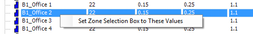
Figure 2.2.1: The Set Zone Selection Box to These Values contextual menu.
There is also a zone filter, located above the two tree views, which allows the user to filter the zones shown in both of the tree views.
If the user wishes to account for any infiltration or ventilation in unheated spaces, they will need to add the applicable zones to the Zones to be Sized tree view, but set the zone’s temperature to -50 °C (-58 °F).