System Components
As explained in Airside Systems, system components can feature in Airside Systems.
They concern the flow of air.
Heating Coil
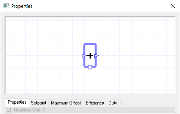
A heating coil is used to warm up the air that passes through it, and can be used with a controller to specify how the component behaves.
If no controller is used, the sensor used to determine the air temperature for the Setpoint field is assumed to be directly after the coil.
Controllers
You can use a controller with the heating coil to control how the coil behaves. For a heating coil, the controller controls the coil by informing it of the amount of power the coil should provide to heat up the air.
The controller does this by sending a signal, between zero and one, to the coil dictating the proportion of the coil’s duty it should use to heat up the air.
So, for example, if the coil received a signal of zero the coil would not warm up the air flowing through it. While if it received a signal of 1, the coil will warm up the air flowing through it using the maximum amount of power allowed from the Duty field.
Properties
Name
This is the name of the component, it will be used in reports or error messages. You can rename components as you wish.
Description
The Description field allows the user to enter a description of the component, which can be useful for keeping notes about the intended operation of the component. By default it is left blank.
Schedule
If a schedule is applied by the user, for all hours outside of the scheduled hours, the component will not operate.
In the case of the heating coil, this will mean that the air will flow through the coil unheated, even if there is a controller sending a non-zero signal to the coil.
The default schedule option is always on, meaning that the component will operate 24/7.
Heating Collection
Once a component is added to a Heating, Fuel or Electrical collection, any heating load it has will be added to that collection’s heating demand in the plant room.
If a component is not assigned to a collection, the energy it uses will be discarded and not reported in the results. Please note you will receive a warning telling you this.
With the Heating Collection, you will be able to join:
Heating groups
Fuel groups
Electrical groups.
Your choice of group will depend on how the heat is being generated. For instance if the heat is being provided to the coil from a boiler, you would choose a Heating group but if the coil was generating the heat itself by burning fuel, you would choose a Fuel group.
Setpoint
When a temperature is entered into the Setpoint field, the component will attempt to regulate the temperature of the air going through it to reach this setpoint.
In the case of the heating coil, it will warm up the air so it reaches the setpoint, but it will not be able to cool down the air to reach the setpoint.
To cool the air you would need another component, for instance a cooling coil.
Please note that when a controller is used in conjunction with the coil, the Setpoint field will disappear from the properties. This is because the coil is being controlled by a controller and will heat up the air when the controller sends a signal informing the coil to do so.
When the Setpoint field is visible, modifiers can be added to the setpoint using the Setpoint tab.
Control Band
When the value of this field is greater than zero, the coil will act as though there is an attached controller monitoring the air temperature immediately after the coil, returning a signal which changes linearly between the two temperatures of “Setpoint” and “Setpoint + Control Band”.
Using the control band field instead of an equivalent controller will result in quicker and more stable simulations, as well as making the system layout less cluttered.
This field is only shown when the coil has no attached controllers, and the duty is not “unlimited”.
Maximum Offcoil
The Maximum Offcoil field of the heating coil specifies the maximum temperature the coil can heat the air passing through it up to, i.e. the maximum temperature of the air coming off the coil.
This field is useful when using a controller to control the coil. As the coil will heat up the air according to the signal from the controller, it is possible that the coil will heat up the air to an undesirable temperature.
Setting a maximum temperature the air can come off the coil at can stop this from happening and can also be used to control the maximum temperature the supply air can be provided at.
Please note that setting the maximum offcoil temperature too low may cause unmet hours and other issues with your results, as the coil won’t be able to warm up the air to a temperature required to condition the zone appropriately.
Also, while there is no need to change this field from the default value when no controller is connected to the coil, if the maximum offcoil temperature is lower than the setpoint temperature the coil will only heat up the air passing through it to the offcoil temperature.
Modifiers can be added to the maximum offcoil temperature using the Maximum Offcoil tab.
Efficiency
The Efficiency field of a heating component only appears when a user chooses:
An electrical group
A fuel group
The “None” option in the Heating Collection field
This is because choosing one of these options allows the user to model a component using its energy source directly at the component to produce heat.
The Efficiency field allows the user to enter how efficient this process is, as a factor.
This field will not have any effect on the air-side results, apart from the consumption results for this component now appearing in the results section of this component.
Please note that while this field appears when the “None” option is chosen in the Heating Collection field, any loads from the component will be discarded as the Heating Collection field is set to “None”.
The user will be able to add a modifier to this field by going to the Efficiency tab, which also appears when the appropriate options are chosen in the Heating Collection Field.
Duty
The duty of a component is the upper limit on the amount of power a component can provide.
If, in a certain hour, the power demand on the component is greater than the duty of the component, the component will not be able to meet this demand. For the heating coil this would mean it wouldn’t be able to heat the air to the setpoint, it would fall short.
In TAS Systems, the demand (or load) met by a component is reported for each hour in the results section. There are 3 options for setting the duty:
Unlimited – Unlimited means the component can meet any demand. Please note that this option cannot be used when a controller is attached to the component.
Sized – Allows the user to size the duty on a design condition. The user will also be asked for a size fraction. Please note that to size the duty the user will need to have design conditions in their systems file.
Value – With this option you can explicitly specify the duty of the component.
In the duty tab, you will be able to choose these 3 options as well, but with the sized and value options you will be able to add a modifier.
Cooling Coil
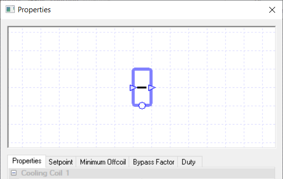
A cooling coil is used to cool the air that passes through it. You can use a controller with the cooling coil to control how the coil behaves.
If no controller is used, the sensor used to determine the air temperature for the Setpoint field is assumed to be directly after the coil.
Controllers
For a cooling coil, the controller controls the coil by informing it of the amount of power the coil should provide to cool down the air. The controller does this by sending a signal, between zero and one, to the coil dictating the proportion of the coil’s duty it should use to cool down the air.
So, for example, if the coil received a signal of zero the coil would not cool down the air flowing through it. If it received a signal of 1 the coil will cool down the air flowing through it using the maximum amount of power allowed from the Duty field.
Properties
Name
This is the name of the component, it will be used in reports or error messages. You can rename components as you wish.
Description
The Description field allows the user to enter a description of the component, which can be useful for keeping notes about the intended operation of the component. By default it is left blank.
Schedule
The Schedule field allows the user to apply a schedule to their component to detail the operational hours of the component.
If a schedule is applied by the user, then they should note that for all hours outside of the scheduled hours, the component will not operate.
In the case of the cooling coil, this will mean that the air will flow through the coil uncooled, even if there is a controller sending a non-zero signal to the coil.
The default schedule option is always on, meaning that the component will operate 24/7.
Cooling Collection
Once a component is added to a Cooling collection, any cooling load it has will be added to that collection’s cooling demand in the plant room.
If a component is not assigned to a collection, the energy it uses will be discarded and not reported in the results; please note you will receive a warning telling you this.
Cooling coils can only join Cooling Groups.
Setpoint
When a temperature is entered into the Setpoint field, the component will attempt to regulate the temperature of the air going through it to reach the setpoint.
In the case of the cooling coil, it will cool the air so it reaches the setpoint, but it will not be able to warm the air to reach this setpoint.
To warm the air you would need another component, for instance a heating coil.
Please note that when a controller is used in conjunction with the coil, the Setpoint field will disappear from the properties. This is done because the coil is being controlled by a controller and will cool down the air when the controller sends a signal informing the coil to do so.
When the Setpoint field is visible, modifiers can be added to the setpoint using the Setpoint tab.
Minimum Offcoil
The Minimum Offcoil field of the cooling coil allows the user to set the minimum temperature the coil can cool the air passing through it down to, i.e. the minimum temperature of the air coming off the coil.
This field is useful when using a controller to control the coil. As the coil will cool down the air according to the signal from the controller, it is possible that the coil will cool down the air to an undesirable temperature.
Setting a minimum temperature the air can come off the coil at can stop this from happening and can also be used to control the minimum temperature the supply air can be provided at.
Please note that setting the minimum offcoil temperature too high may cause unmet hours and other issues with your results, as the coil won’t be able to cool down the air to a temperature required to condition the zone appropriately.
Also, while there is no need to change this field from the default value when no controller is connected to the coil, if the minimum offcoil temperature is higher than the setpoint temperature the coil will only cool down the air passing through it to the offcoil temperature.
Modifiers can be added to the minimum offcoil temperature using the Minimum Offcoil tab.
Bypass Factor
The Bypass Factor field determines the amount of air that will bypass the coil and thus will not be cooled by the coil.
The value is entered as a factor between 0 and 1 and this factor is then multiplied against the flow rate of the air, just before the coil, to determine the amount of air that will bypass the coil.
Modifiers can be added to the bypass factor using the Bypass Factor tab.
The Bypass Factor has an effect on the latent cooling load.
If part of an incoming warm airflow is bypassing the coil then in order for the overall temperature to reach the cooling setpoint, the air which does not bypass the coil must be cooled below the coil’s cooling setpoint, and the temperature of the air is therefore more likely to drop down to its Dewpoint. As a result, higher bypass factors tend to imply higher latent loads.
Duty
The duty of a component is the upper limit on the amount of power a component can provide.
If, in a certain hour, the power demand on the component is greater than the duty of the component, the component will not be able to meet this demand.
For the cooling coil this would mean it wouldn’t be able to cool the air to the setpoint, it would fall short. In TAS Systems, the demand (or load) met by a component is reported for each hour in the results section. There are 3 options for setting the duty:
Unlimited – Unlimited means the component is always able to meet the demand. Please note that this option cannot be used when a controller is attached to the component.
Sized – Allows the user to size the duty on a design condition. The user will also be asked for a size fraction. Please note that * Value – With this option the user will type in the duty of the component.
In the Duty tab, you will be able to choose these 3 options as well, but with the sized and value options you will be able to add a modifier.
DX Coil
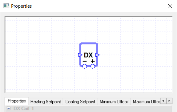
The DX coil component allows the user to model heating and cooling of the air by refrigerants.
Controllers
The DX coil can be used in conjunction with two controllers, one to control the coil’s heating and one to control the coil’s cooling.
When using a controller to control the coil’s heating, otherwise known as a heating controller, please create/connect it by using the circle underneath the plus sign.
Similarly with a cooling controller, please create/connect to the circle underneath the minus sign.
How the signal affects the DX coil depends on what option the user chooses in the Control Method field; please see that field’s section below for more details.
If no controller is used with the DX coil, the sensor used to determine the air temperature for the Setpoint fields is assumed to be directly after the coil.
Note
If the DX coil tries to both heat and cool the air in the same hour, either due to conflicting signals from its controllers or overlapping Setpoint fields, your system will produce an error during simulation.
Properties
Name
This is the name of the component, it will be used in reports or error messages. You can rename components as you wish.
Description
The Description field allows the user to enter a description of the component, which can be useful for keeping notes about the intended operation of the component. By default it is left blank.
Schedule
The Schedule field allows the user to apply a schedule to their component to detail the operational hours of the component.
If a schedule is applied by the user, then they should note that for all hours outside of the scheduled hours, the component will not operate.
In the case of the DX coil, this will mean that the air will flow through the coil unconditioned, even if there is a controller sending a non-zero signal to the coil.
The default schedule option is always on, meaning that the component will operate 24/7.
Refrigerant Collection
Once a component is added to a Refrigerant collection, any heating or cooling load it has will be added to that collection’s refrigerant demand in the plant room.
If a component is not assigned to a collection, the energy it uses will be discarded and not reported in the results.
As the DX coil uses refrigerants, you can only join refrigerant Groups.
Heating/Cooling Setpoints
When a temperature is entered into the Setpoint field, the component will attempt to regulate the temperature of the air going through it to reach this setpoint. As the DX coil can provide both heating and cooling, you will have separate temperature setpoints for heating and cooling.
When the air temperature is less than the heating setpoint, the DX coil will warm up the air to the setpoint. When the air temperature is above the cooling setpoint, the DX coil will cool the air down to the cooling setpoint.
If the air temperature is between the heating and cooling setpoint, the DX coil will not heat or cool the air.
Note
The cooling setpoint should always be a higher temperature than the heating setpoint. If this is not the case then you will receive an overlapping limits error as your DX coil will be trying to heat and cool the air at the same time.
Please note that when a controller is used in conjunction with the DX coil, the Setpoint fields will disappear from the properties. This is because the DX coil’s heating / cooling is being controlled by a controller. This means the DX coil will condition the air according to the signal it’s sent rather than to the air temperature.
It should also be noted that you cannot mix between controller and setpoint control. So, for instance, you cannot have the DX coil heating mode controlled by the Heating Setpoint field while the cooling mode is controlled by a controller.
When the Setpoint fields are visible, modifiers can be added to the setpoints using the appropriate Setpoint tab.
Control Method
The Control Method field only appears in the DX coil’s properties list when a controller is attached to the component. It allows the user to decide how the coil will work when it receives a signal from a controller. The user can choose from the following two methods:
Partload
On/Off
Partload
The Partload option allows the DX coil to run at a partload to meet a demand for the hour. The partload the DX coil runs at depends on the controller and the signal. The heating controller controls the coil by informing it of the amount of power the coil should provide to heat up the air. The controller does this by sending a signal, between zero and one, to the coil dictating the proportion of the coil’s heating duty it should use to heat up the air.
So, for example, if the coil received a signal of zero the coil would not warm up the air flowing through it. If it received a signal of 1 the coil will warm up the air flowing through it using the maximum amount of power allowed from the Heating Duty field.
Similarly the cooling controller controls the coil by informing it of the amount of power the coil should provide to cool down the air. The controller does this by sending a signal, between zero and one, to the coil dictating the proportion of the coil’s cooling duty it should use to cool down the air.
So, for example, if the coil received a signal of zero the coil would not cool down the air flowing through it. If it received a signal of 1 the coil will cool down the air flowing through it using the maximum amount of power allowed from the Cooling Duty field.
On / Off
With this option the DX coil will only operate at full duty to meet any heating or cooling demand. The signal in this case informs the DX coil of the demand it must meet. In hours where it only needs to be partially on to meet the demand, TAS will model the unit as on at maximum for the required period and off for the rest of the hour. It will then take the average results over the hour (both the on and off period) and report them in the result section.
Minimum Offcoil
The Minimum Offcoil field of the DX coil allows the user to set the minimum temperature the coil can cool the air passing through it down to, i.e. the minimum temperature of the air coming off the coil.
This field is useful when using a controller to control the coil. As the coil will cool down the air according to the signal from the controller, it is possible that the coil will cool down the air to an undesirable temperature.
Setting a minimum temperature the air can come off the coil at can stop this from happening and can also be used to control the minimum temperature the supply air can be provided at.
Please note that setting the minimum offcoil temperature too high may cause unmet hours and other issues with your results, as the coil won’t be able to cool down the air to a temperature required to condition the zone appropriately.
Also, while there is no need to change this field from the default value when no controller is connected to the coil, if the minimum offcoil temperature is higher than the setpoint temperature the coil will only cool down the air passing through it to the offcoil temperature.
Modifiers can be added to the minimum offcoil temperature using the Minimum Offcoil tab.
Maximum Offcoil
The Maximum Offcoil field of the DX coil allows the user to set the maximum temperature the coil can heat the air passing through it up to, i.e. the maximum temperature of the air coming off the coil.
This field is useful when using a controller to control the coil. As the coil will heat up the air according to the signal from the controller, it is possible that the coil will heat up the air to an undesirable temperature.
Setting a maximum temperature the air can come off the coil at can stop this from happening and can also be used to control the maximum temperature the supply air can be provided at.
Please note that setting the maximum offcoil temperature too low may cause unmet hours and other issues with your results, as the coil won’t be able to warm up the air to a temperature required to condition the zone appropriately.
Also, while there is no need to change this field from the default value when no controller is connected to the coil, if the maximum offcoil temperature is lower than the setpoint temperature the coil will only heat up the air passing through it to the offcoil temperature.
Modifiers can be added to the maximum offcoil temperature using the Maximum Offcoil tab.
Bypass Factor
When the DX coil is cooling the air, the bypass factor helps to determine the amount of air that will bypass the coil and thus will not be heated or cooled by the coil.
The value is entered as a factor between 0 and 1 and this factor is then multiplied against the flow rate of the air just before the coil to determine the amount of air that will bypass the coil.
Modifiers can be added to the bypass factor using the Bypass Factor tab.
The Bypass Factor has an effect on the latent cooling load. If part of an incoming warm airflow is bypassing the coil then in order for the overall temperature to reach the cooling setpoint, the air which does not bypass the coil must be cooled below the coil’s cooling setpoint, and the temperature of the air is therefore more likely to drop down to its Dewpoint. As a result, higher bypass factors tend to imply higher latent loads.
Heating & Cooling Duty
The duty of a component is the upper limit on the amount of power a component can provide.
If, in a certain hour, the power demand on the component is greater than the duty of the component, the component will not be able to meet this demand.
In TAS Systems, the demand (or load) met by a component is reported for each hour in the results section.
Please note that for a DX Coil, the heating and cooling duties are set separately. This allows you to model a refrigerant coil that just provides heating or cooling by setting the other’s duty to zero.
In TAS Systems, there are 3 options for the duty:
Unlimited – Unlimited means the component is always able to meet the demand. Please note that this option cannot be used when a controller is attached to the component.
Sized – Allows the user to size the duty on a design condition. The user will also be asked for a size fraction. Please note that to size the duty the user will need to have design conditions in their systems file.
Value – With this option the user will type in the duty of the component.
In the duty tab, you will be able to choose these 3 options as well, but with the sized and value options you will be able to add a modifier.
Junction
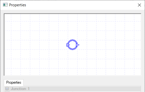
The Junction has two uses. The first use is to model where the fresh air enters the system and where the exhaust air leaves the system. In these cases the junction will only have one duct connected to it and it will turn blue, to indicate it is an external junction.
The second use of a junction is to split or merge air paths. When being used to split up an air path, the user may need to use a damper or fan on the new air paths to set the design flow rates along these new paths.
You cannot use controllers with junctions.
Properties
Name
This is the name of the component, it will be used in reports or error messages. You can rename components as you wish.
Description
The Description field allows the user to enter a description of the component, which can be useful for keeping notes about the intended operation of the component. By default it is left blank.
Steam Humidifier
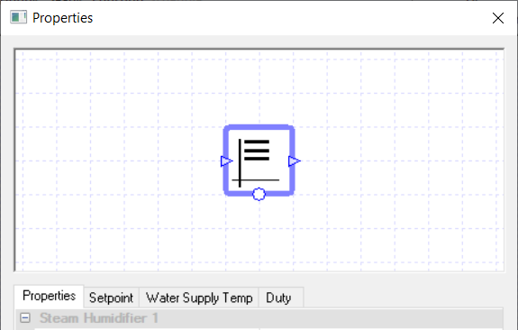
A steam humidifier increases the humidity of the air passing through it by adding steam to it.
Please note that this process humidifies the air while keeping the air temperature constant.
Controllers
You can use a controller with the steam humidifier to control how the humidifier behaves.
For a steam humidifier, the controller controls the humidifier by informing it of the amount of power the humidifier should provide to humidify the air.
The controller does this by sending a signal, between zero and one, to the humidifier dictating the proportion of the humidifier’s duty it should use to humidify the air.
So, for example, if the humidifier received a signal of zero the humidifier would not humidify the air flowing through it.
If it received a signal of 1 the humidifier will humidify the air flowing through it using the maximum amount of power allowed from the Duty field.
If no controller is used, the sensor used to determine the relative humidity for the Setpoint field is assumed to be directly after the Humidifier.
Properties
Name
This is the name of the component, it will be used in reports or error messages. You can rename components as you wish.
Description
The Description field allows the user to enter a description of the component, which can be useful for keeping notes about the intended operation of the component. By default it is left blank.
Schedule
The Schedule field allows the user to apply a schedule to their component to detail the operational hours of the component.
If a schedule is applied by the user, then they should note that for all hours outside of the scheduled hours, the component will not operate.
In the case of the steam humidifier, this will mean that the air will flow through the humidifier without being humidified, even if there is a controller sending a non-zero signal to the humidifier.
The default schedule option is always on, meaning that the component will operate 24/7.
Electrical Collection
Once a component is added to an electrical collection, any electrical load it has will be added to that collection’s electrical demand in the plant room.
If a component is not assigned to a collection, the energy it uses will be discarded and not reported in the results.
The Steam Humidifier component in TAS Systems can only join Electrical Groups.
Water Supply temperature
The Water Supply Temperature field allows the user to specify the temperature of the water being supplied to the humidifier.
Please note that as the supply water temperature increases, the energy demand of the steam humidifier decreases. This is because less energy is required to produce the steam.
There are 2 options for setting the water supply temperature:
Value – With this option the user will type in the water supply temperature. Modifiers can be added to the water supply temperature using the Water Supply Temp tab.
As Ground Water Temperature – With this option the water supply temperature will be equal to the “Water Temp” specified in the “External Conditions” section of the “Simulate” dialog.
RH Setpoint
When a Relative Humidity (RH) is entered into the RH setpoint field, the component will increase the RH of the air to this setpoint.
If the air’s RH is greater than the RH setpoint, there will be no change in the humidity of the air as the steam humidifier does not dehumidify the air.
Please note that when a controller is used in conjunction with the steam humidifier, the Setpoint field will disappear from the properties.
This is because the steam humidifier is being controlled by a controller and will humidify the air when the controller sends a signal informing the humidifier to do so.
When the RH Setpoint field is visible, modifiers can be added to the setpoint using the Setpoint tab.
Duty
The duty of a component is the upper limit on the amount of power a component can provide.
If, in a certain hour, the power demand on the component is greater than the duty of the component, the component will not be able to meet this demand.
For a humidifier this would mean it wouldn’t be able to increase the RH of the air to the setpoint, it would fall short.
In TAS Systems, the demand (or load) met by a component is reported for each hour in the results section. There are 3 options for setting the duty:
Unlimited – Unlimited means the component is always able to meet the demand. Please note that this option cannot be used when a controller is attached to the component.
Sized – Allows the user to size the duty on a design condition. The user will also be asked for a size fraction. Please note that to size the duty the user will need to have design conditions in their systems file.
Value – With this option the user will type in the duty of the component.
In the duty tab, you will be able to choose these 3 options as well, but with the sized and value options you will be able to add a modifier.
Spray Humidifier
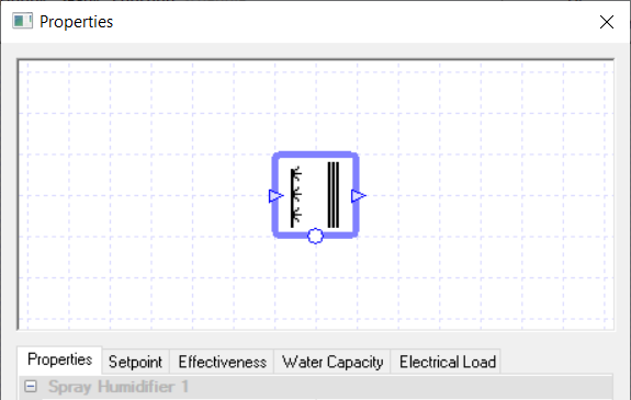
A spray humidifier increases the humidity of the air by spraying water into it.
The spray humidifies the air by evaporative cooling, meaning the spray humidifier humidifies along lines of constant enthalpy on the Psychrometric Chart.
Controllers
You can use a controller with the spray humidifier to control how the humidifier behaves.
For a spray humidifier, the controller controls the humidifier by informing it of the amount of water it should add to the air to humidify it.
The controller does this by sending a signal, between zero and one, to the humidifier dictating the proportion of the humidifier’s water flow capacity it should use as the water flow rate to humidify the air.
So, for example, if the humidifier received a signal of zero the humidifier would not humidify the air flowing through it.
If it received a signal of 1, the humidifier will humidify the air flowing through it by adding the maximum amount of water allowed from the Water Flow Capacity field.
If no controller is used, the sensor used to determine the relative humidity for the RH Setpoint field is assumed to be directly after the humidifier.
Properties
Name
This is the name of the component, it will be used in reports or error messages. You can rename components as you wish.
Description
The Description field allows the user to enter a description of the component, which can be useful for keeping notes about the intended operation of the component. By default it is left blank.
Schedule
The Schedule field allows the user to apply a schedule to their component to detail the operational hours of the component.
If a schedule is applied by the user, then they should note that for all hours outside of the scheduled hours, the component will not operate.
In the case of the spray humidifier, this will mean that the air will flow through the humidifier without being humidified, even if there is a controller sending a non-zero signal to the humidifier.
The default schedule option is always on, meaning that the component will operate 24/7.
Electrical Collection
Once a component is added to an electrical collection, any electrical load it has will be added to that collection’s electrical demand in the plant room.
If a component is not assigned to a collection, the energy it uses will be discarded and not reported in the results.
The Spray Humidifier component in TAS Systems can only join Electrical Groups.
RH Setpoint
When a relative humidity is entered into the RH Setpoint field, the component will increase the RH of the air to this setpoint.
If the air’s RH is greater than the RH setpoint, there will be no change in the humidity of the air as the spray humidifier does not dehumidify the air.
Please note that when a controller is used in conjunction with the humidifier, the Setpoint field will disappear from the properties. This is because the humidifier is being controlled by a controller and will humidify the air when the controller sends a signal informing the humidifier to do so.
When the RH Setpoint field is visible, modifiers can be added to the setpoint using the Setpoint tab.
Effectiveness
This option allows the user to input how effective the spray humidifier is.
The effectiveness needs to be entered as a factor between 0 and 1.
The effectiveness of the spray humidifier can be found using the following formula:
Where \(T\) is the air temperature and \(H\) is the humidity ratio The subscript on each letter denotes where the measurement was taken – \({in}\) denotes that the measurement is taken on the air entering the spray humidifier. \({out}\) denotes that the measurement is taken on the air exiting the spray humidifier. \({sat}\) denotes the temperature or humidity ratio when the air would be saturated when following the line of constant enthalpy.
In the Effectiveness tab you are able to apply a modifier to this field.
Water Flow Capacity
The Water Flow Capacity field allows the user to enter the Water Flow Capacity of the Steam Humidifier.
If the water flow capacity is set too low, the humidifier will not be able to humidify the air to the setpoint.
In TAS Systems there are 3 options to choose from to set the water flow capacity:
Unlimited – This means there is no limit on the water flow, meaning the humidifier can spray as much water into the air as it needs to. Please note that this option cannot be used when a controller is connected to the component.
Value – The user can enter a value to provide a maximum limit to the water flow.
Sized - Allows the user to size the Water Flow Capacity on a design condition. The user will also be asked for a size fraction. Please note that to size the duty the user will need to have design conditions in their systems file.
In the Water Flow Capacity tab, you will have these 3 options as well, but with the sized and value options you will be able to add a modifier.
Electrical Load
The Electrical Load field of the spray humidifier allows the user to account for any electrical load in the exchanger, for instance the load associated with spraying the water into the air stream.
This load is then passed onto the plant room collection, which is chosen in the Electrical Collection field.
The user can type in a value into this field and the component will pass this amount of electrical load onto the plant room collection for each hour of the simulation.
As it is very unlikely that the user will want to pass on the same load for every hour of the simulation, it is recommended that the user goes to the Electrical Load tab and creates a modifier for this field. With the various modifiers available, the user will be able to vary the loads throughout the simulation.
Load Component
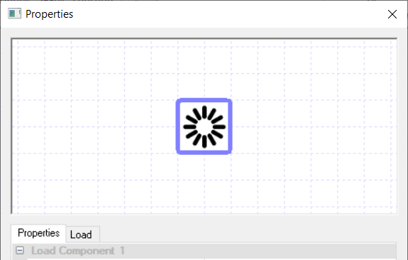
The Load component is a stand-alone component that allows the user to model additional loads that will not be modelled as a part of their air side system.
The additional load modelled by the component is then added to the plant room collection chosen in the Collection field, so that the software can include it in the energy consumption calculations.
As the Load component is a stand-alone component, it has no ports on it to connect up to air-side systems and also cannot be used with controllers.
Properties
Name
This is the name of the component, it will be used in reports or error messages. You can rename components as you wish.
Description
The Description field allows the user to enter a description of the component, which can be useful for keeping notes about the intended operation of the component. By default it is left blank.
Collection
In the Collection field, the user will be able to choose one of the plant room collections they have created in their plant room system.
When a collection is chosen, any load entered into this component for the hour will be passed onto the collection and will be reported in the collection’s demand.
Method
The load can either be entered directly, using the “Load” option, or a flow rate and fluid details can be entered, from which a load will be calculated automatically during the simulation.
Load
The Load field allows the user to enter in the amount of load they would like the component to pass onto the plant room collection.
The user can type in a value into the field and the component will pass this amount of load onto the plant room collection for each hour of the simulation.
As it is very unlikely that the user will want to pass on the same load for every hour of the simulation, it is recommended that the user goes to the Load tab and creates a modifier for this field. With the various modifiers available, the user will be able to vary the loads throughout the simulation.
This property and tab are only visible when the “Load” option is selected for the “Method”.
Flow Rate
This field allows the user to enter in the fluid flow rate they would like to use to calculate a load to pass onto the plant room collection.
As it is very unlikely that the user will want to use the same flow rate for every hour of the simulation, it is recommended that the user goes to the Flow Rate tab and creates a modifier for this field. With the various modifiers available, the user will be able to vary the flow rate throughout the simulation.
This property and tab are only visible when the “Flow Rate” option is selected for the “Method”.
Delta T
The change in fluid temperature used to calculate the load to pass on to the plant room collection.
This property is only visible when the “Flow Rate” option is selected for the “Method”.
Specific Heat Capacity
The fluid specific heat capacity used to calculate the load to pass on to the plant room collection.
This property is only visible when the “Flow Rate” option is selected for the “Method”.
Density
The fluid density used to calculate the load to pass on to the plant room collection.
This property is only visible when the “Flow Rate” option is selected for the “Method”.
Fan
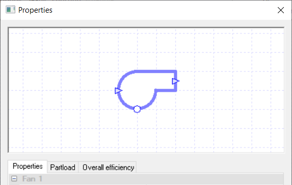
The Fan component in TAS Systems is one of the fundamentals of any system that requires air flow through ducts, as it is the fan component that provides this air flow.
Due to this, any system that cannot be represented by an unconnected zone component will need at least one Fan component within the system.
For more information, see Airside Systems.
Controllers
Controllers can be used with the Fan component, and they will control how much pressure the fan will exert on the air flowing through it.
The signal received by the fan dictates the pressure increase caused by the fan. Please note that this pressure increase is not the value entered in the fan’s Pressure field. Instead the software will calculate the maximum pressure increase from the Pressure field of the fan and the design flow rates and design pressure drops of other components around the system.
Also, as pressure and flow rate are linked, controlling the pressure with a controller will also mean that the flow rate will vary. If it is only the fans, and not the dampers, with controllers attached, how the signal received by the fan affects the flow rate is shown using the equation below:
Please note that fans and dampers, being controlled by different controllers, can be used in conjunction to model certain systems; for instance a VAV system. In this instance the fan’s controller will control the pressure increase through the fan while the damper’s controller will control the capacity through the damper.
The flow rate in this instance will not be controlled by either controller on its own; it will be the result of the pressures and capacities around the system.
Please see the examples in the TAS Systems Controller guide for more on how to do this.
Properties
Name
This is the name of the component, it will be used in reports or error messages. You can rename components as you wish.
Description
The Description field allows the user to enter a description of the component, which can be useful for keeping notes about the intended operation of the component. By default it is left blank.
Schedule
The Schedule field allows the user to apply a schedule to their component to detail the operational hours of the component.
If a schedule is applied by the user, then they should note that for all hours outside of the scheduled hours, the component will not operate.
In the case of the fan, this will mean that the fan will not provide any air flow.
If all fans in your system are scheduled to be off in the same hour then there will be no air flow in your system.
The default schedule option is always on, meaning that the component will operate 24/7.
Electrical Collection
Once a component is added to an electrical collection, any electrical load it has will be added to that collection’s electrical demand in the plant room.
If a component is not assigned to a collection, the energy it uses will be discarded and not reported in the results.
Fans in TAS Systems can only join Electrical groups.
Design Flow Source
See Fan Design Flow Source for details.
Minimum Flow Source
The Minimum Flow Source option only appears when a controller is attached to the fan, as this option is only required when the flow rate is varying.
The Minimum Flow Source option allows the user to choose how they wish to set the minimum flow rate of the system.
The Minimum Flow Source option gives the same options as the Design Flow Source option but instead sets the Minimum Flow Rate field. Please note there are some differences between the two:
The ‘none’ option does not give you any other options. It means that the flow rate can decrease as needed.
The ‘All Attached Zones Sized’ and ‘Nearest Zone Sized’ methods come with 4 sizing methods to choose from: Hourly Person, Hourly Person and Area, Hourly IC – Outside Air, and Hourly IC – Ventilation. These sizing methods work like the peak methods but are calculated each hour, allowing the user to model systems with a variable fresh air requirement based on occupancy.
All options, apart from the ‘none’ option, allow for a minimum design flow fraction to be set. The minimum design flow fraction allows the user to set the minimum flow rate as a fraction of the design flow rate. Please note that if the minimum design flow fraction and the minimum flow rate both have values in them, TAS will take the maximum of the two as the minimum flow rate. It will also enter the maximum into the Minimum Flow Rate field after a simulation.
To ensure that the minimum flow rate set here is met, TAS works out the signal the fan requires to meet this flow rate and then sets it as the minimum signal of all attached controllers, ensuring the flow rate doesn’t drop below this level. It is recommended that all fans on the same air path have the same minimum flow rate.
Overall Efficiency
- The overall efficiency of the fan is the product of its:
Motor efficiency
Electrical efficiency
Belt efficiency
Aerodynamic efficiency (as there will be aerodynamic losses in the fan)
This does not include any partload efficiency, which is set by the Partload field. The user will need to enter the overall efficiency as a factor between zero and one.
Heat Gain Factor
The heat gain factor of the fan is the proportion of energy used to power the fan that is converted to heat. The generated heat will warm up the air that passes through the fan.
Partload
Clicking on the Partload field will take you to the Partload tab. From this tab, you will be able to edit the Partload profile of the component by using the graph or the table.
To see how to edit the Partload profiles, please watch the Profiles video in the TAS Systems User Guide.
Pressure
The fan pressure is related to the SFP of the fan, and can be entered here. Please see Specific Fan Power in Airside Systems for more details.
Damper
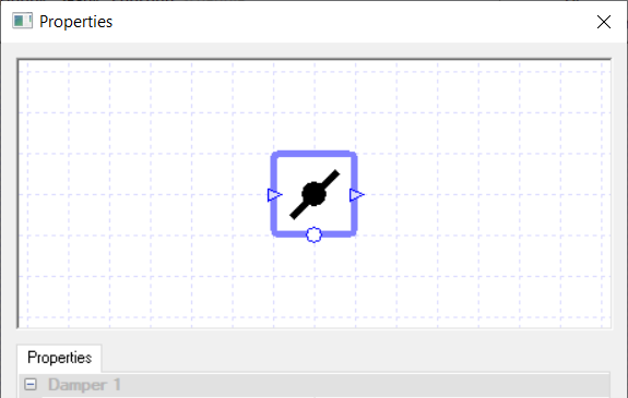
The Damper component in Systems is used to regulate the air flow. They are mainly used after splitting up air paths to modulate the air flow on each path.
Controllers
Controllers can be used with the damper, and they will control the capacity of the damper.
The signal the component receives dictates the proportion of the maximum capacity that the damper will close to, where the maximum capacity is set by either the Design Flow Rate field or the Capacity field of the damper.
So for example, if the damper receives a signal of 1 from the controller, the damper will open up and allow air through it according to its maximum capacity.
If the damper receives a signal of zero from the controller, the damper will close completely and will not allow any air to pass through it.
It should be noted that as the capacity of the damper varies, so will the flow rate and pressure of the system.
Please note that Fans and Dampers, being controlled by different controllers, can be used in conjunction to model certain systems; for instance a VAV system. In this instance the fan’s controller will control the pressure increase through the fan while the damper’s controller will control the capacity through the damper. The flow rate in this instance will not be controlled by either controller on its own; it will be the result of the pressures and capacities around the system.
Please see the examples in the TAS Systems Controller guide for more on how to do this.
Properties
Name
This is the name of the component, it will be used in reports or error messages. You can rename components as you wish.
Description
The Description field allows the user to enter a description of the component, which can be useful for keeping notes about the intended operation of the component. By default it is left blank.
Schedule
The Schedule field allows the user to apply a schedule to their component to detail the operational hours of the component.
If a schedule is applied by the user, then they should note that for all hours outside of the scheduled hours, the component will not operate.
In the case of the damper, this will mean that the damper will close and will not allow any air to flow through it. This will mean any other component on the same air path as the damper will not receive any air flow in this hour.
The default schedule option is always on, meaning that the component will operate 24/7.
Design Flow Source
See Fan Design Flow Source for details.
Design Pressure Drop
The Design Pressure Drop field, like the Design Flow Rate field, is used during the design flow calculations to fix the capacity of the damper; if the user has not already fixed the capacity.
The field sets the drop in pressure, at the design flow rate, of the air as it passes through the damper.
The user has the following two options to choose from in this field:
None
Value
None
When this option is chosen, TAS will calculate the pressure drop through the component in a similar manner to how it calculates all other pressure drops through the other air – side components.
Value
When this option is chosen, the user is required to enter in the pressure drop at the damper.
This pressure drop cannot be bigger than or equal to the sum of all fan components’ Pressure fields.
If the air will flow through multiple dampers/ air-side economisers, then the sum of these components’ Design Pressure Drop fields must not be bigger than or equal to the sum of all fan components’ pressure fields. Entering in a higher value will lead to an error calculating the capacities within the user’s system.
The value entered here will be the pressure drop when the flow rate is at the design flow rate.
Please note that if you have a variable flow rate, the pressure drop will be bigger or smaller for decreased flow rates depending on if it is the damper or the fan varying the flow rate.
Minimum Flow Source
The Minimum Flow Source option only appears when a controller is attached to the damper, as this option is only required when varying the flow rate at a damper.
This option allows the user to choose how they wish to set the minimum flow rate of the air path the damper is on. The user should note that when using the damper to vary the flow rate they will also need to control the pressure of any fan in the system; an example of how to do this can be found in the TAS Systems Controller guide.
The Minimum Flow Source option gives the same options as the Design Flow Source option but instead sets the minimum flow source. Please note that there are some differences between the options:
The ‘none’ option does not give you any other options. It means that the flow rate can decrease as needed.
The ‘All Attached Zones Sized’ and ‘Nearest Zone Sized’ methods come with 4 sizing methods to choose from: Hourly Person, Hourly Person and Area, Hourly IC – Outside Air, and Hourly IC – Ventilation. These sizing methods work like the peak methods but are calculated each hour, allowing the user to model systems with a variable fresh air requirement based on occupancy.
All options, apart from the ‘none’ option, allow for a minimum design flow fraction to be set. The minimum design flow fraction allows the user to set the minimum flow rate as a fraction of the design flow rate. Please note that if the minimum design flow fraction and the minimum flow rate both have values in them, TAS will take the maximum of the two as the minimum flow rate. It will also enter the maximum into the Minimum Flow Rate field after a simulation.
To ensure that the minimum flow rate is met, TAS works out the signal the damper requires to meet this flow rate and then sets it as the minimum signal of all attached controllers, ensuring the flow rate doesn’t drop below this level.
It is recommended that all fans on the same air path have the same minimum flow rate.
Design Flow Capacity Signal
The Design Flow Capacity Signal option only appears when a controller is attached to the component.
The design flow capacity signal allows the user to make the design flow rate of the damper correspond to a certain signal from the controller.
For instance if the Design Flow Capacity Signal field has the value x entered into it then when the controller’s signal reads x, the flow rate through the damper will be the design flow rate. By design the factor is set to one by default and it is recommended that it is kept that way.
Air-Side Economiser
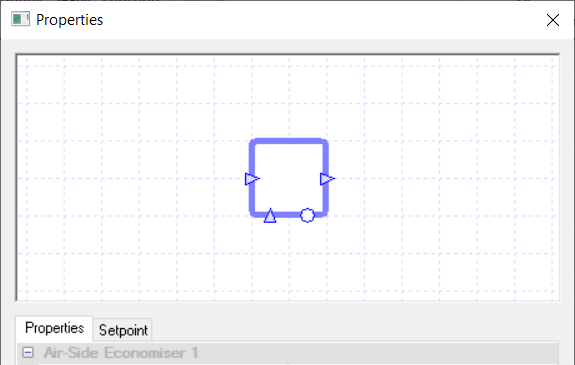
An air-side economiser should be used in circuits where the air is being re-circulated.
The user can set up the minimum amount of fresh air that must enter the circuit along with a target temperature to aim for when mixing the air streams together.
As the air-side economiser controls the flow rate, you do not need to use a damper with it. Please note that the air-side economiser takes the air entering the port on the side as being fresh air and the air entering the port at the bottom as the re-circulated air.
Controllers
Controllers can be used with the air-side economiser, and they will control how much the air-side economiser will mix the two air streams together.
If a Setpoint Passthrough Standard controller is connected to the air-side economiser, then the signal sent to the air-side economiser will not be between zero and one but instead be the reading taken by the sensor. This reading is then used as the temperature setpoint the air-side economiser will attempt to mix the two air streams to.
If a Standard controller sending a signal between zero and one is attached to the air-side economiser, the signal specifies the proportion of re-circulated air in the system.
A signal of zero means that the air-side economiser will only allow for fresh air to enter the system while a signal of one means that the air-side economiser will only allow for the minimum amount of fresh air to enter the system with the rest being re-circulated. A signal in-between the two indicates the two streams are being mixed, with a lower signal implying that more fresh air makes up the supply air.
If no controller is used, the sensor used to determine the air temperature for the Setpoint field is assumed to be placed in the supply air directly after the air-side economiser. It should be noted that the air-side economiser assumes that there are no flow components between the input ducts and the nearest junctions; these input ducts are highlighted in blue on the screenshot below:
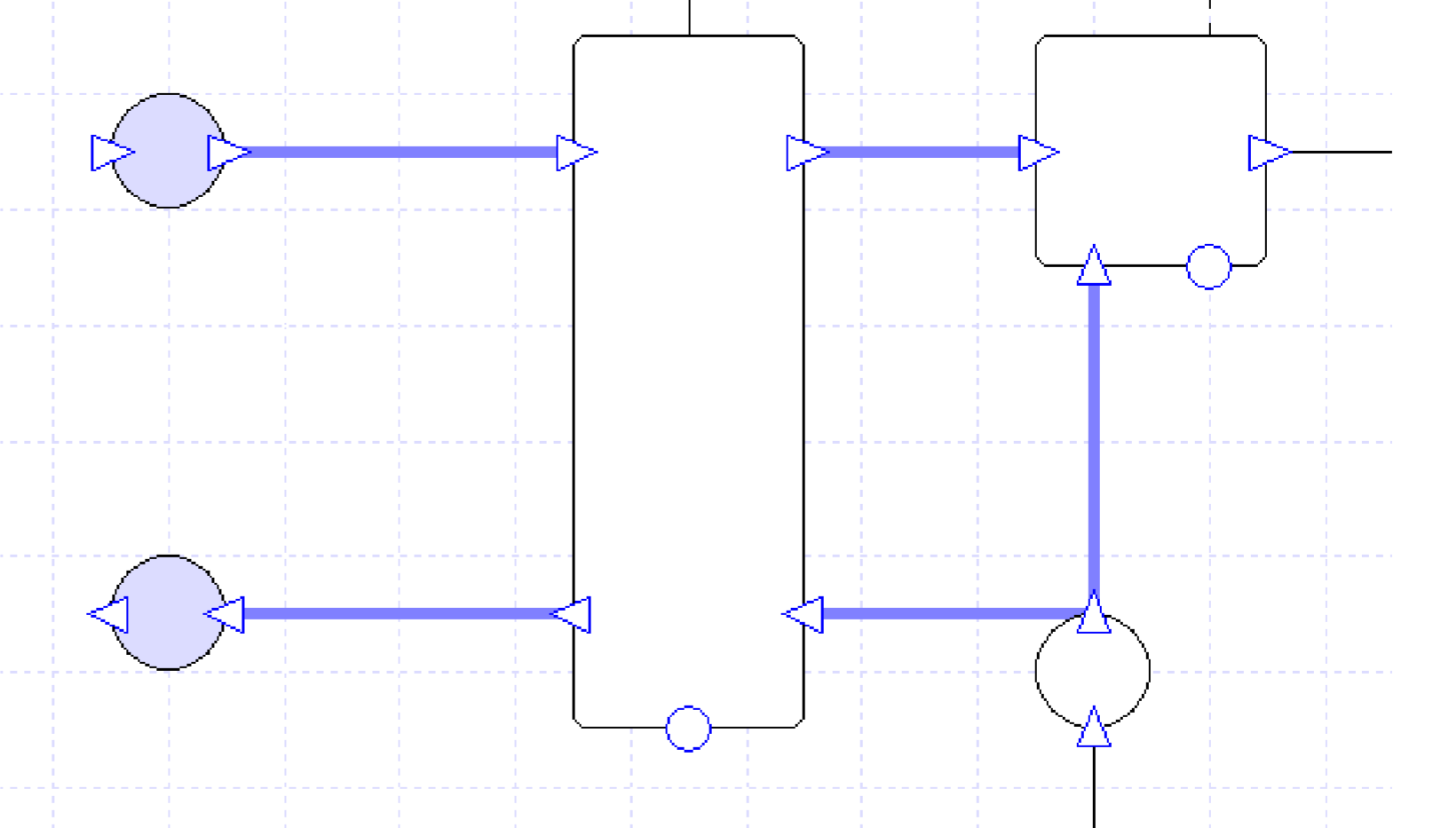
Placing a flow component on these ducts will cause issues with how the air-side economiser works; for instance, the minimum fresh air requirement may not be met.
Properties
Name
This is the name of the component, it will be used in reports or error messages. You can rename components as you wish.
Description
The Description field allows the user to enter a description of the component, which can be useful for keeping notes about the intended operation of the component. By default it is left blank.
Schedule
This option allows the user to apply a schedule to the air-side economiser. The way the Air-Side Economiser component works with the Schedule field is unique compared to the other components.
During scheduled hours the air-side economiser will operate by mixing the two air streams such that the minimum fresh air requirement is always met. During the out of schedule hours, the air-side economiser will operate according to the choice set in the “Mode When Off” property.
Design Flow Source
See Fan Design Flow Source for details.
Minimum Fresh Air Source
The Minimum Fresh Air Source option allows the user to choose how they wish to obtain the minimum fresh air rate.
The minimum fresh air rate is the minimum amount of fresh air that the air-side economiser will add to the re-circulated air, where the fresh air is the air coming from the duct connected to the input port on the side of the air-side economiser.
The options to choose from are the same as the Design Flow Source options, except:
The ‘none’ option means that there is no requirement that fresh air is added to the circuit. This could mean for days on end no fresh air would enter the circuit.
The ‘All Attached Zones Sized’ and ‘Nearest Zone Sized’ methods come with three additional sizing methods: Hourly Person, Hourly Person and Area, and Hourly Internal Condition. These sizing methods work like the peak methods but are calculated each hour, allowing the user to model systems with a variable fresh air requirement based on occupancy.
Design Pressure Drop
See Design Pressure Drop for details.
Setpoint
When a temperature is entered into the setpoint field, the component will attempt to regulate the temperature of the air going through it to reach this setpoint.
In the case of the air-side economiser, it will try to merge the two air streams together to reach the setpoint. As the air-side economiser has no heating or cooling capability, it will not always be able to meet this setpoint.
Please note that when a controller is used in conjunction with the air-side economiser, the Setpoint field will disappear from the properties. This is done because the air-side economiser is being controlled by a controller and will mix the air streams based on the signal sent by the controller. When the Setpoint field is visible, modifiers can be added to the setpoint using the Setpoint tab.
Mode When Off
The Mode When Off property only appears in the air-side economiser’s properties when a schedule other than “Always On” is applied.
The property allows the user to set how the air-side economiser works during out of schedule hours when the fans are active and creating an air flow. These out of scheduled hours will depend on the schedule chosen by the user in the Schedule field.
The user gets three options with this field:
Through – The “Through” option tells the air-side economiser that during un-scheduled hours the air should not be re-circulated and any air flow needed should be provided by fresh air.
Recirc – The “Recirc” option tells the air-side economiser that during un-scheduled hours the air should be re-circulated only, no fresh air should be introduced.
Minimum – The “No Minimum” option tells the air-side economiser that during un-scheduled hours it can still mix the air streams to reduce the loads, but it no longer needs to meet the minimum fresh air requirement.
Fresh Air Mixing Box
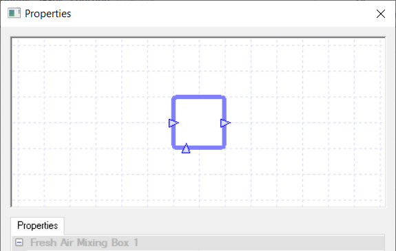
A fresh air mixing box is a simplified version of the air-side economiser.
Instead of varying the amount of fresh air introduced into the system to reduce any heating/cooling loads, the fresh air mixing box will always bring in the amount of fresh air specified in the Minimum Fresh Air field during scheduled hours (i.e. it acts like an air-side economiser which has a controller always sending a signal of one).
Due to the fresh air mixing box not mixing the two air streams to meet a temperature it does not have a setpoint field and cannot be connected to a controller. However, apart from the above differences, the properties of the fresh air mixing box are the same as the air side economiser and will not be discussed in this section.
Exchanger
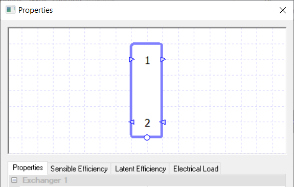
A heat exchanger allows for the transfer of heat from one air stream to another air stream.
The ports at the top should be used for the supply air, while the ports at the bottom should be used for the exhaust air.
You can input both the sensible and latent efficiencies of the exchanger.
Controllers
Controllers can be used with the heat exchanger, and they will control how much the exchanger will exchange heat between the two air streams.
If a Setpoint Passthrough Standard controller is connected to the heat exchanger, then the signal sent to the exchanger will not be between zero and one but instead the reading taken by the sensor. This reading is then used as the temperature setpoint the exchanger will attempt to get the supply air to.
If a Standard controller sending a signal between zero and one is attached to the exchanger the signal specifies the proportion of exhaust air, on the lower air path, that flows through the exchanger.
A signal of zero means that all exhaust air will bypass the exchanger, stopping any heat transfer, while a signal of one means that all exhaust air will flow through the exchanger, allowing for the maximum amount of heat transfer to take place. A signal in-between the two implies a partial bypass of the exhaust air, with a lower signal indicating more exhaust air bypassing the exchanger and reducing the amount of heat transfer.
Please note that if a controller isn’t used and the Setpoint field is set to on, the sensor determining the air temperature for the Setpoint field is assumed to be placed directly after the component in the supply air (after the exit port on the top).
Properties
Name
This is the name of the component, it will be used in reports or error messages. You can rename components as you wish.
Description
The Description field allows the user to enter a description of the component, which can be useful for keeping notes about the intended operation of the component. By default it is left blank.
Schedule
The Schedule field allows the user to apply a schedule to their component to detail the operational hours of the component.
If a schedule is applied by the user, then they should note that for all hours outside of the scheduled hours, the component will not operate. In the case of the exchanger, this will mean that the exchanger will not exchange heat between the two air streams. Instead the air streams will just flow through the exchanger unaltered.
The default schedule option is always on, meaning that the component will operate 24/7.
Calculation Method
See Calculation Method for details.
Latent Method
See Latent Method for details.
Setpoint
With the exchanger, you have two options with the Setpoint: None or On.
Upon choosing the “None” option, the heat exchanger will exchange heat depending on the rate of heat transfer calculated from the calculation method.
Upon choosing the “On” option, you will be asked to enter a temperature as its value.
When a temperature is entered into the Setpoint Value field, the component will attempt to regulate the temperature of the air going through it, by allowing the exhaust air to bypass the exchanger, so that the supply air leaving the exchanger is at this setpoint.
In the case of the exchanger it will transfer heat to warm up or cool down the supply air to the setpoint. As the exchanger only transfers heat from the hotter air mass to the cooler one, sometimes it will not be able to meet the temperature setpoint. Factors that will affect this include: the fresh air and extract air temps and the maximum rate of heat transfer.
Please note that when a controller is used in conjunction with the heat exchanger, the Setpoint field will disappear from the properties. This is done because the air-side economiser is being controlled by a controller and will exchange heat between the air streams based on the signal sent by the controller.
When the Setpoint field is visible, modifiers can be added to the setpoint using the Setpoint tab.
Electrical Collection
Collections are a way of grouping components that share the same source of energy. Once a component is added to an electrical collection, any electrical load it has will be added to that collection’s electrical demand in the plant room.
If a component is not assigned to a collection, the energy it uses will be discarded and not reported in the results.
For the heat exchanger, the electrical collection chosen here will have the loads entered in the Electrical Load field passed onto it.
Electrical Load
The Electrical Load field of the heat exchanger allows the user to account for any electrical load in the exchanger, for instance from the pump for the run around coil.
This load is then passed onto the plant room collection, which is chosen in the Electrical Collection field. The user can type in a value into this field and the component will pass this amount of electrical load onto the plant room collection for each hour of the simulation.
As it is very unlikely that the user will want to pass on the same load for every hour of the simulation, it is recommended that the user goes to the Load tab and creates a modifier for this field. With the various modifiers available, the user will be able to vary the loads throughout the simulation.
Heating Only
When this tick box is ticked, the heat exchanger will only be able to exchange heat if this will warm up the supply air.
If your heat exchanger can exchange heat to both heat and cool down the supply air, then you should leave this option un-ticked.
Adjust Setpoint for Economiser
When this tick box is ticked and there is an air-side economiser directly after the heat exchanger, the exchanger will try and exchange heat between the air streams to control the temperature of the air after the air-side economiser to the temperature entered into the Setpoint field.
Doing this eliminates the rare scenarios where the heat exchanger and air side economiser could fight against each other, increasing the heating and cooling loads.
Desiccant Wheel
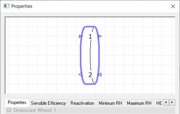
A desiccant wheel is a rotary heat exchanger with a coating of desiccant on it.
The supply air for the zone should use the top ports of the desiccant wheel while the exhaust air should use the bottom ports.
When one of the air streams is at a temperature, set by the reactivation profile, such that the desiccant is fully reactivated then the desiccant wheel allows for heat and moisture to be transferred between the two air streams along lines of constant enthalpy.
When both air streams temperatures are at a temperature such that the desiccant is not reactivated at all, the desiccant wheel acts like a heat exchanger.
Depending on the profile used for the reactivation, the desiccant can be partially reactivated. When the desiccant is partially reactivated the desiccant wheel’s properties are a mixture of when the desiccant is fully reactivated and when the desiccant is not reactivated at all.
Please note that a controller cannot be used with a desiccant wheel.
Properties
Name
This is the name of the component, it will be used in reports or error messages. You can rename components as you wish.
Description
The Description field allows the user to enter a description of the component, which can be useful for keeping notes about the intended operation of the component. By default it is left blank.
Schedule
The Schedule field allows the user to apply a schedule to their component to detail the operational hours of the component.
If a schedule is applied by the user, then they should note that for all hours outside of the scheduled hours, the component will not operate.
In the case of the desiccant wheel, this will mean that the desiccant wheel will not exchange heat or moisture between the two air streams. Instead the air streams will just flow through the desiccant wheel unaltered. The default schedule option is always on, meaning that the component will operate 24/7.
Sensible Efficiency
This field sets the sensible efficiency of the desiccant wheel when the desiccant is fully reactivated. The sensible efficiency is calculated by the following formula when the supply air’s flow rate is equal to the exhaust air’s flow rate:
Where \(T_{\text{supply}}\) is the temperature of the supply air immediately after going through the exchanger, \(T_{\text{return}}\) is the temperature of the return air before entering the exchanger and \(T_{\text{fresh}}\) is the temperature of the supply air before entering the exchanger.
In the rare cases where the exchanger is used with the air entering it at the top and bottom at different flow rates, the efficiency is worked out with the following equation:
Where \(T_{\text{aft.}}\) is the temperature of the air exiting the exchanger on the selected air flow, \(T_{\text{bef.}}\) is the temperature of the air entering the exchanger on the selected air flow, \(Q\) is the flow rate of the selected air flow, \(\min{(x,y)}\) means the smaller of the two values and the subscript \(\text{f1}\) and \(\text{f2}\) relate to whether it is the first or second air stream this value should be taken from.
This equation will sometimes give you a negative efficiency, which would be caused in this case by the air stream \(f1\) transferring heat to the air stream \(f2\). The efficiency entered into the efficiency field should always be the absolute value.
Minimum RH
This field sets the minimum relative humidity that either airstream can leave the desiccant wheel with when the desiccant is reactivated.
Please note that the user can place a modifier on this field using the Minimum RH tab.
Maximum RH
This field sets the maximum relative humidity that either airstream can leave the desiccant wheel with when the desiccant is reactivated.
Please note that the user can place a modifier on this field using the Maximum RH tab.
Reactivation
The Reactivation field takes the user to the Reactivation tab where they are asked to create a profile to set up when the desiccant is reactivated.
When using the profile, an entry of zero for the Reactivation field indicates when the desiccant is not reactivated. This means that the desiccant wheel acts as a heat exchanger using the properties from the Heat Exchanger fields.
An entry of one in the Reactivation field indicates when the desiccant is fully reactivated. This means the desiccant wheel transfers both heat and moisture along lines of constant enthalpy and uses the Sensible Efficiency and RH fields.
Values in the reactivation field between zero and one indicate where the desiccant is partially reactivated. In this case the desiccant wheel uses a mixture of both properties.
By default a profile has been set up based on dry bulb temperature, as the reactivation profile would normally have the desiccant activated at higher dry bulb temperatures. TAS will only match the air stream (supply or exhaust) with the highest temperature against the profile.
Please note that while technically you could delete the profile and enter a value in for the Reactivation field, it is not recommended to do so and you will receive a warning if you try.
Heat Exchanger Efficiency (sensible)
This field allows the user to input the sensible efficiency of the desiccant wheel when the desiccant is not activated.
The sensible efficiency of the desiccant wheel is calculated by the following formula when the supply air’s flow rate is equal to the exhaust air’s flow rate:
Where \(T_{\text{supply}}\) is the temperature of the supply air immediately after going through the exchanger, \(T_{\text{return}}\) is the temperature of the return air before entering the exchanger and \(T_{\text{fresh}}\) is the temperature of the supply air before entering the exchanger.
In the rare cases where the desiccant wheel is used with the air entering at the top and bottom of the desiccant wheel at different flow rates, the efficiency is worked out with the following equation:
Where \(T_{\text{aft.}}\) is the temperature of the air exiting the exchanger on the selected air flow, \(T_{\text{bef.}}\) is the temperature of the air entering the exchanger on the selected air flow, \(Q\) is the flow rate of the selected air flow, \(\min{(x,y)}\) means the smaller of the two values and the subscript \(\text{f1}\) and \(\text{f2}\) relate to whether it is the first or second air stream this value should be taken from.
This equation will sometimes give you a negative efficiency, which would be caused in this case by the air stream \(f1\) transferring heat to the air stream \(f2\). The efficiency entered into the efficiency field should always be the absolute value.
The user can place a modifier on this field using the HE eff (Sensible) tab.
Heat Exchanger Efficiency (latent)
This field allows the user to input the latent efficiency of the desiccant wheel when the desiccant is not activated.
The latent efficiency is calculated by the following formula when the supply air’s flow rate is equal to the exhaust air’s flow rate:
Where \(\text{Supply HR}\) is the humidity ratio of the supply air immediately after going through the desiccant wheel, \(\text{Return HR}\) is the return humidity ratio of the return air before entering the desiccant wheel and the \(\text{Fresh Air HR}\) is the humidity ratio of the supply air before entering the desiccant wheel.
In the rare cases where the desiccant wheel is used with the air entering at the top and bottom of the desiccant wheel at different flow rates, the latent efficiency is worked out with the following equation:
Where \(\text{HR}_{\text{aft}}\) is the humidity ratio of the air exiting the exchanger on the selected air flow, \(\text{HR}_{\text{bef}}\) is the humidity ratio of the fluid entering the exchanger on the selected air flow, \(Q\) is the flow rate of the selected air flow, Min(x ,y) means to take the minimum value of the two entries, and the subscript \(f1\) and \(f2\) relates as to whether it is the first or second air stream this value should be taken from.
Please note that this equation will sometimes give you a negative efficiency, which would be caused in this case by the air stream \(f1\) transferring heat to the air stream \(f2\).
The efficiency entered into the Efficiency field should always be the absolute value.
The user can place a modifier on this field using the HE eff (latent) tab.
Heat Exchanger Temperature Setpoint
This field allows the user to input the optional temperature setpoint of the desiccant wheel when the desiccant is not activated.
You have two options with the Setpoint: None or On.
Upon choosing the ‘none’ option, the desiccant wheel will exchange heat depending on the rate of heat transfer calculated from the Heat Exchanger Efficiency (Sensible) field.
Upon choosing the ‘On’ option, you will be asked to enter a temperature as its value. When a temperature is entered into the setpoint value field, the component will attempt to regulate the temperature of the air going through it to reach this setpoint.
In the case of the desiccant wheel, it will transfer heat from the hotter air flow to the cooler one to warm up or cool down the supply air to the setpoint.
As this field is only used by the desiccant wheel when it is in heat exchanger mode, sometimes it will not be able to meet the temperature setpoint. Factors that will affect this include: the fresh air and extract air temps and the maximum rate of heat transfer.
Electrical Collection
Collections are a way of grouping components that share the same source of energy.
Once a component is added to an electrical collection, any electrical load it has will be added to that collection’s electrical demand in the plant room.
If a component is not assigned to a collection, the energy it uses will be discarded and not reported in the results.
For the desiccant wheel, the electrical collection chosen here will have the loads entered in the Electrical load field passed onto it.
Electrical Load
The Electrical Load field of the desiccant wheel allows the user to account for any electrical load in the desiccant wheel, for instance from the wheel’s motor.
This load is then passed onto the plant room collection, which is chosen in the Electrical Collection field. The user can type in a value into this field and the component will pass this amount of electrical load onto the plant room collection for each hour of the simulation.
As it is very unlikely that the user will want to pass on the same load for every hour of the simulation, it is recommended that the user goes to the Load tab and creates a modifier for this field. With the various modifiers available, the user will be able to vary the loads throughout the simulation.
System Zone
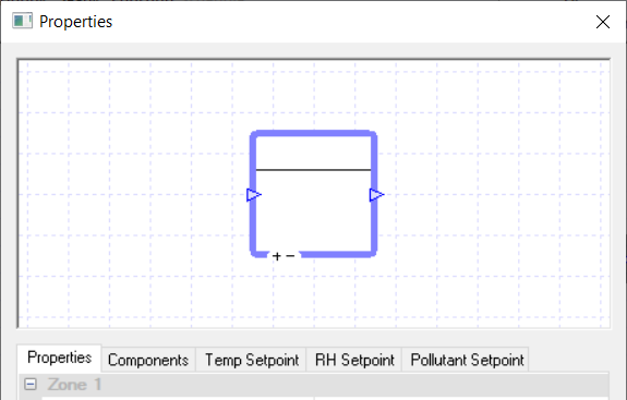
The System Zone Component in TAS Systems is used to model a zone’s placement in the systems schematic.
The user will need to drag a zone from the TSD Data folder (from the Project Explorer in Systems and not from the TSD itself) onto the System Zone to tell TAS Systems what zone the component is modelling.
If the user groups some components together, and the group includes a System Zone, they can then drag a Zone Group onto the grouped components to model an air handling unit serving multiple zones.
Please note that you can drag and drop Zone Components from the library into the System Zone. These Zone Components will be discussed separately.
While you cannot use a controller with the System Zone, you can connect sensors from other controllers to the zone by placing the controller on the +- symbol at the bottom of the System Zone.
Properties
Name
This is the name of the component, it will be used in reports or error messages. You can rename components as you wish.
Description
The Description field allows the user to enter a description of the component, which can be useful for keeping notes about the intended operation of the component. By default it is left blank.
DHW Collection
Collections are a way of grouping components that share the same source of energy.
Once a System Zone is added to a DHW collection, any DHW load the zone has (decided by the zone’s internal condition in the TBD) will be added to that collection’s DHW demand in the plant room.
If a component is not assigned to a collection, the energy it uses will be discarded and not reported in the results. For a System Zone, the DHW demand can only be placed in DHW groups.
Equipment Electrical Collection
Collections are a way of grouping components that share the same source of energy.
Once a System Zone is added to an Equipment Electrical Collection, any electrical load from equipment the zone has (decided by the equipment gains from the zone’s internal condition in the TBD) will be added to that collection’s electrical demand in the plant room.
If a component is not assigned to a collection, the energy it uses will be discarded and not reported in the results. For a System Zone, the equipment electrical demand can only be placed in Electrical groups.
Lighting Electrical Collection
Collections are a way of grouping components that share the same source of energy.
Once a System Zone is added to a Lighting Electrical Collection, any electrical load from the lighting the zone has (decided by the lighting gains from the zone’s internal condition in the TBD) will be added to that collection’s electrical demand in the plant room.
If a component is not assigned to a collection, the energy it uses will be discarded and not reported in the results. For a System Zone, the lighting electrical demand can only be placed in Electrical groups.
Zone
The Zone field displays the name of the zone being modelled by the component.
It is greyed out in the properties list as it cannot be edited from here. To change the zone being modelled by the component, the user should select the new zone from the TSD data folder and drag and drop it onto the component.
Displacement Vent
The Displacement Ventilation option allows the user to model displacement ventilation in their zone by ticking this option.
With displacement ventilation, your conditioned cool supply air is supplied to the zone at floor level while warmer air is extracted from the zone at ceiling level.
Please note that when using the Displacement Ventilation option in conjunction with zone components, the effect of the displacement ventilation will only occur in the hours the zone components are not actively meeting any heating or cooling demand.
System Modelled Interzone Flows
This option only affects models with IZAMs.
When the option is ticked, TAS Systems will ignore any IZAMs in the TBD and the air movement will have to be modelled in TAS Systems. If the option is un-ticked then the IZAMs will be taken into account.
The default option for this field is un-ticked.
System Modelled Vent Flows
This option affects the ventilation values in the Internal Condition for each zone.
When this option is ticked, TAS Systems will ignore the ventilation values in the TBD and the ventilation will have to be modelled in TAS Systems.
The default option for this is ticked.
Flow Rate
Fresh Air Rate
The Fresh Air Rate field of a zone is a parameter that can be used by flow components (fans, dampers and air-side economisers) to help set the minimum fresh air requirement for the system.
Please note that just entering a value here does not mean that this will be the amount of fresh air supplied to the zone. Instead it will depend on your system set up, especially the flow component setup.
There are three options for setting the Fresh Air Rate field of a System Zone. On the whole, the three methods are exactly the same as discussed in the Flow Rate Field. With the sizing method however, there are an extra 4 sizing methods to choose from:
Hourly Person
Hourly Person and Area
Hourly IC – Outside Air
Hourly IC – Ventilation.
These sizing methods work like the peak methods but are calculated for each hour, allowing the user to model systems with a variable fresh air requirement based on occupancy.
Direct Evaporative Cooler
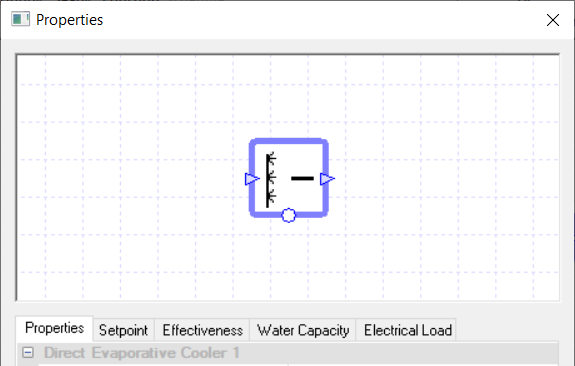
A direct evaporative cooler cools the air flowing through it by spraying water into it.
The spray cools the air by evaporative cooling, leading to an increase of humidity along lines of constant enthalpy on the Psychrometric Chart.
Controllers
You can use a controller with the direct evaporative cooler to control how the cooler behaves.
For a direct evaporative cooler, the controller controls the cooler by informing it of the amount of water it should add to the air to cool it. The controller does this by sending a signal, between zero and one, to the cooler dictating the proportion of the cooler’s water flow capacity it should use as the water flow rate to cool the air.
So, for example, if the cooler received a signal of zero the cooler would not cool the air flowing through it. While if it received a signal of 1, the cooler will cool the air flowing through it by adding the maximum amount of water allowed from the Water Flow Capacity field.
If no controller is used, the sensor used to determine the temperature for the Setpoint field is assumed to be directly after the cooler.
Properties
Name
This is the name of the component, it will be used in reports or error messages. You can rename components as you wish.
Description
The Description field allows the user to enter a description of the component, which can be useful for keeping notes about the intended operation of the component. By default it is left blank.
Schedule
The Schedule field allows the user to apply a schedule to their component to detail the operational hours of the component.
If a schedule is applied by the user, then they should note that for all hours outside of the scheduled hours, the component will not operate.
In the case of the direct evaporative cooler, this will mean that the air will flow through the cooler without being cooled, even if there is a controller sending a non-zero signal to the cooler.
The default schedule option is always on, meaning that the component will operate 24/7.
Electrical Collection
Collections are a way of grouping components that share the same source of energy.
Once a component is added to an electrical collection, any electrical load it has will be added to that collection’s electrical demand in the plant room.
If a component is not assigned to a collection, the energy it uses will be discarded and not reported in the results.
The Direct Evaporative Cooler component in TAS Systems can only join Electrical Groups.
Setpoint
When a temperature is entered into the Setpoint field, the component will attempt to regulate the temperature of the air going through it to reach the setpoint.
In the case of the direct evaporate cooler, it will cool the air so it reaches the setpoint, but it will not be able to warm the air to reach this setpoint. To warm the air you would need another component, for instance a heating coil.
Please note that when a controller is used in conjunction with the cooler, the Setpoint field will disappear from the properties. This is done because the cooler is being controlled by a controller and will cool down the air when the controller sends a signal informing the coil to do so.
When the Setpoint field is visible, modifiers can be added to the setpoint using the Setpoint tab.
Effectiveness
This option allows the user to input how effective the direct evaporative cooler is.
The effectiveness needs to be entered as a factor between 0 and 1. The effectiveness of the direct evaporative cooler can be found using the following formula:
Where \(T\) is the air temperature and \(H\) is the humidity ratio. Please note that the subscript on each letter denotes where that measurement is taken. A \(in\) subscript in denotes that the measurement is taken on the air entering the direct evaporative cooler; an \(out\) subscript out denotes that the measurement is taken on the air exiting the direct evaporative cooler and the \(sat\) subscript denotes the temperature or humidity ratio of when the air would be saturated when following the line of constant enthalpy.
In the Effectiveness tab you are able to apply a modifier to this field.
Water Flow Capacity
The Water Flow Capacity field allows the user to enter the Water Flow Capacity of the direct evaporative cooler.
If the water flow capacity is set too low, the cooler will not be able to cool the air to the setpoint.
In TAS Systems there are 3 options to choose from to set the water flow capacity:
Unlimited – This means there is no limit on the water flow, meaning the cooler can spray as much water into the air as it needs to. Please note that this option cannot be used when a controller is connected to the component.
Value – The user can enter a value to provide a maximum limit to the water flow.
Sized - Allows the user to size the Water Flow Capacity on a design condition. The user will also be asked for a size fraction. Please note that to size the duty the user will need to have design conditions in their systems file.
In the Water Flow Capacity tab, you will have these 3 options as well, but with the sized and value options you will be able to add a modifier.
Electrical Load
The Electrical Load field of the direct evaporative cooler allows the user to account for any electrical load in the cooler, for instance the load associated with spraying the water into the air stream.
This load is then passed onto the plant room collection, which is chosen in the Electrical Collection field. The user can type in a value into this field and the component will pass this amount of electrical load onto the plant room collection for each hour of the simulation.
As it is very unlikely that the user will want to pass on the same load for every hour of the simulation, it is recommended that the user goes to the Electrical Load tab and creates a modifier for this field.
With the various modifiers available, the user will be able to vary the loads throughout the simulation.
Tank Volume
The Tank Volume field requires the user to enter the volume of the evaporative dry cooler’s tank.
Hours Before Purging Tank
The Hours Before Purging Tank field allows the user to enter the number of hours the cooler will be inactive for before the tank is emptied.
If zero is entered into this field, then the tank will never be purged.