Examples
This section of the guide will work through some worked examples which should aid the user’s understanding of how the controller set up works.
High Limit Temperature Shut-Off
In this example, we will model an optimiser with a high limit temperature shut-off in a system with recirculation.
We require this optimiser to shut off when the external air’s dry bulb temperature is at or above 21°C.
When the optimiser is shut-off, the optimiser will not mix fresh air with the exhaust air to try and temper the air to the supply air’s temperature (thus reducing the loads at the coil) but instead recirculate most of the air while bringing in the minimum amount of fresh air required by the zones in this system.
Modelling in Systems
This shut off can be easily achieved if we tell the optimiser to mix to the exhaust air’s temperature in these shut-off hours.
As the exhaust air is already at this temperature, the optimiser will only mix in the minimum amount of fresh air if a value is set in the Minimum Fresh Air field of the optimiser. However, during normal operation we require the optimiser to mix the fresh and exhaust air together to try and meet the supply air temperature after it has been conditioned; to reduce the loads on the coils doing this conditioning.
We can easily tell the optimiser to mix to a certain temperature by using a standard controller of type “Setpoint Passthrough”. We can also select what signal to send to the optimiser, based on the external air temperature, by using an If controller in conjunction with a Standard controller of Normal type.
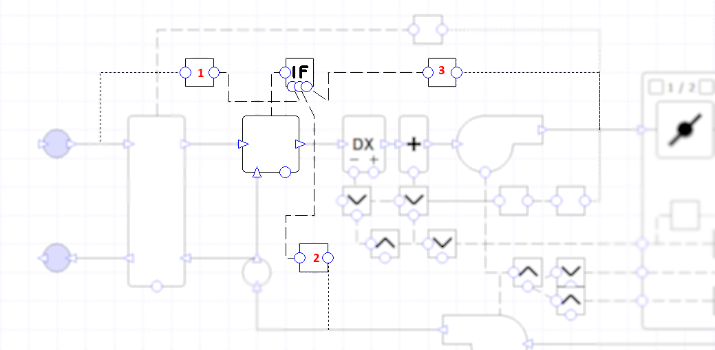
Figure 19 - The If controller setup for the high temperature shut-off. Please note that all blurred controllers and components are not used in setting up the shut-off.
The If controller, denoted in Figure 19 as the controller with the symbol “IF”, is connected to the optimiser while reading the signals of 3 chained controllers.
The first of these chained controllers, labelled 1 in Figure 19, is the controller with its sensor reading the fresh air temperature.
To get the results we desire, we want the If controller only to produce the two signals of the chained controllers in the second and third ports. This means that this first chained controller must only produce a signal of zero or one.
Also we want the first chained controller to produce a signal of one when the external air temperature is at or above 21°C and a signal of zero when it is below this temperature, so the If controller takes the correct signal from the chained controllers to use.
We also require this controller to be chained to the If controller using the bottom left port, as it is the condition controller. To set up this controller correctly, you will need to use a Standard controller of Normal type. The Variable field in the controller properties should be set to temperature and the sensor should be attached to the duct immediately after the inlet junction.
The controller’s signal profile should be set up as per Figure 20:
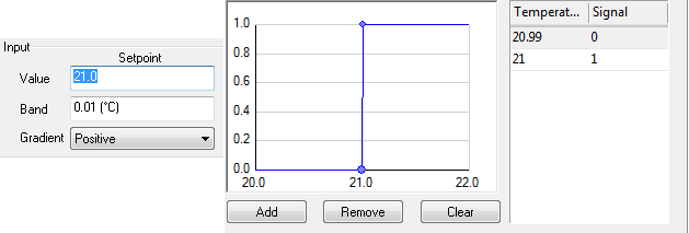
Figure 20 - Set up of the fresh air controller, this has a narrow band due to being required to produce a signal of zero and one
The narrow band is required as this controller must only produce a signal of zero or one. A band of 0.01 (°C) is used because in most cases the external air temperature provided from the weather data only gives temperature to one decimal place.
The second of the controllers, labelled 2 in Figure 19 and attached to the middle port, will be used to produce a signal from the exhaust air’s temperature.
This controller should be a standard controller of type “Setpoint Passthrough” with the Variable field set to “Temperature”; the sensor for this controller should be placed on the exhaust air duct. As we require the use of the exact exhaust air temperature here, the user should not enter an offset on this controller.
The third and final chained controller, labelled 3 and attached to the port on the right, has the same set up as the second controller apart from the sensor is attached to the supply air of the zone, after any conditioning to the air has been done and before the air is supplied to the zone.
Explanation
When the external air temperature is below 21°C, the first chained controller to the If controller will produce a signal of zero.
This zero signal is then read by the If controller, which then takes the signal from controller 3 as its signal and passes this onto the optimiser.
As the signal from controller 3 is the temperature of the supply air after it has been conditioned, the optimiser will attempt to mix the fresh air and exhaust air to meet this temperature.
When the external air temperature is at or above 21°C, the first chained controller to the If controller will produce a signal of one.
This signal of one is then read by the If controller, which then takes the signal from controller 2 as it’s signal and passes it onto the optimiser.
As this signal from controller 2 is the temperature of the exhaust air, the optimiser will only add the minimum amount of fresh air mandated at the optimiser to the system, as required by the shut-off.
AHU Heating and Cooling Setup
In this example, we want to model a central AHU supplying conditioned air (hot or cold) to attached zones. The central AHU will have sensors reading the temperature in each zone, while also having a backup space heating device in each zone.
This backup heating device will activate if the AHU can’t supply enough hot air to keep the zone’s temperature above the lower limit of the temperature thermostat. However, there is no backup cooling device in the space. So if the supplied conditioned air cannot cool the space below the upper limit of the thermostat, the space will overheat.
Due to this, we will require that the AHU prioritises any space needing cooling over zones requiring heating as these zones can use their in zone heating component to provide this heating. Also, to stop the zones from potentially overheating, if one zone does not require heating then the AHU should not warm up the supply air.
Note
We recommend users put zones with similar demands (roughly requiring heating or cooling in the same hours) on the same system.
In previous versions of TAS, the user would also have to set up another controller so they could control the temperature the supply air was being supplied at. Since V9.2.1.7, this no longer the case as all coils now have an Offcoil property which limits the maximum or minimum temperature the coils can heat or cool to.
Modelling in Systems
To know when to heat and cool the air depending on the zones demands, we are going to need to attach 2 controllers to each zone. Each controller will need to read the zone’s dry bulb air temperature and produce a signal based on either the upper or lower limit of the zone’s thermostat.
We will need one controller that produces a signal of 1 when the zone requires heating (a heating controller) and another that produces a signal of 1 when the zone requires cooling (a cooling controller). This can easily be done with a Standard controller using the thermostat options to produce a signal.
Prioritising the cooling load over the heating load requires more thought. Firstly, the coils cannot be directly attached to all the appropriate controllers. Having multiple controllers connected to one component will lead to the component being controlled incorrectly. We will need to collate all the results from the controllers reporting the signal for heating and cooling separately and then get one signal out from them.
This can be done with Max and Min controllers. With the AHU, we want the cooling coil to operate when one of the zones has a cooling demand. This will mean we will want to take the maximum signal produced from any of the cooling controllers and pass that onto the cooling coil. The Cooling coil will then proportion its load in relation to this signal and cool the air down to condition this space. This can be easily done by using a Max controller.
With the heating coil, we only want it to operate when all of the zones have a heating demand. This means that we want to take the minimum signal produced from each zones heating controller, as if a zone doesn’t require heating there will be a zero signal produced by the heating controller. This can be easily done by using a Min controller.
Using the Minimum and Maximum controllers like this means that the AHU prioritises cooling over heating, as required.
Note
When setting up the bands in the heating and cooling controllers, these bands should never overlap in such a way that both controllers will produce a non-zero signal in the same hour. Doing this could lead to the supply air being heated and cooled in the same hour, wasting energy and slowing down the simulation at the same time.
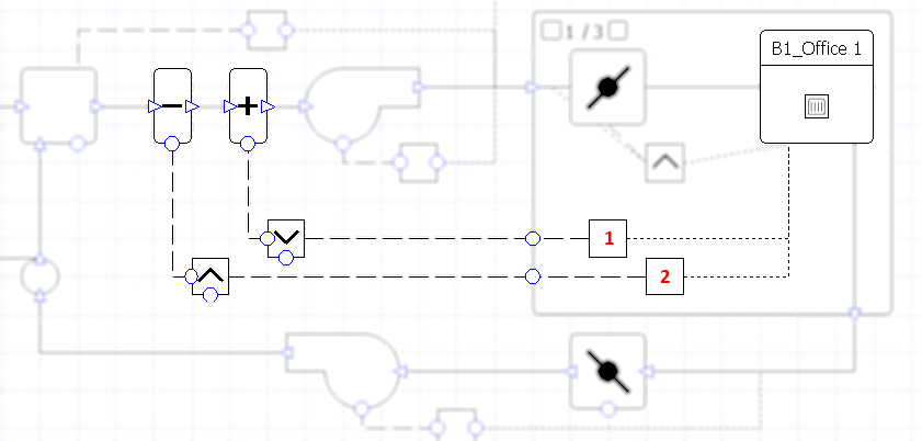
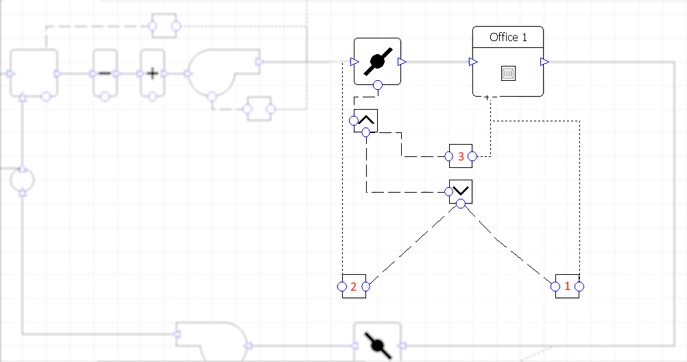
Figure 21 - The controller setup for the heating and cooling coils in the AHU. Faded components are not required in this setup.
The controllers, labelled 1 and 2 in Figure 21, are unique to each zone. As the AHU has been modelled using a group of zones, each zone will have two similar controllers attached to it.
The controller with label 1 in Figure 21 is the heating controller for that zone. The controller is a Standard controller of Normal type. Its Variable field is set to Temperature (thermostat) and it is producing a signal profile using the lower limit of the zone’s temperature thermostat. Its one sensor is attached to the zone and is reading the dry bulb temperature of the zone. The profile is set up as shown in Figure 22.
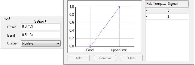
Figure 23- Setup of the cooling controller
As you can see from Figure 23, the profile works in the following way; the controller produces signal of one when the temperature is above the upper limit of the thermostat.
The produced signal reduces with the requirement of cooling, as the room decreases in temperature until the zone’s temperature is 0.5°C below the upper limit. At this temperature, the signal reaches the minimum and stays there for any lower temperature.
So now we have set up the heating and cooling controllers, all that needs to be done is to connect them up. For the cooling control we need to connect all the cooling controllers up to a Max controller which in turn is connected to a cooling coil.
Similarly we need to connect all heating controllers up to a minimum controller which in turn is connected to a heating coil.
The user should note that when using a group of components to represent multiple zones, they would set up one heating and cooling controller connected to Min and Max controllers along with sensors connected to the zone component. They would then group the controllers with the zone component and apply a zone group to the grouped controllers. This will model the multiple zones, with multiple controllers feeding into a Max or Min controller.
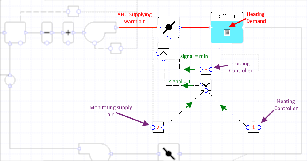
Explanation
When all zones are below the lower limit of their thermostats, their heating controllers will send a signal of one to the Min controller while the cooling controllers will send a signal of zero onto the Max controller. Due to this, the Min controller will send a signal of one to the heating coil and the Max controller will send a signal of zero to the cooling coil. This will mean that the AHU will heat the air to condition the spaces but will not cool it.
In the situation where one (or more) of the zone’s temperature goes above the temperature lower limit + 0.5°C, the heating controller of the zone will produce a signal of zero. When all the heating controller signals are passed onto the Min controller, this signal of zero will ensure that the Min controller sends a signal of zero to the heating coil. This means that the heating coil will not heat the air so that it doesn’t overheat the zone not requiring heating. The in-space heating components will have to cover this heating demand.
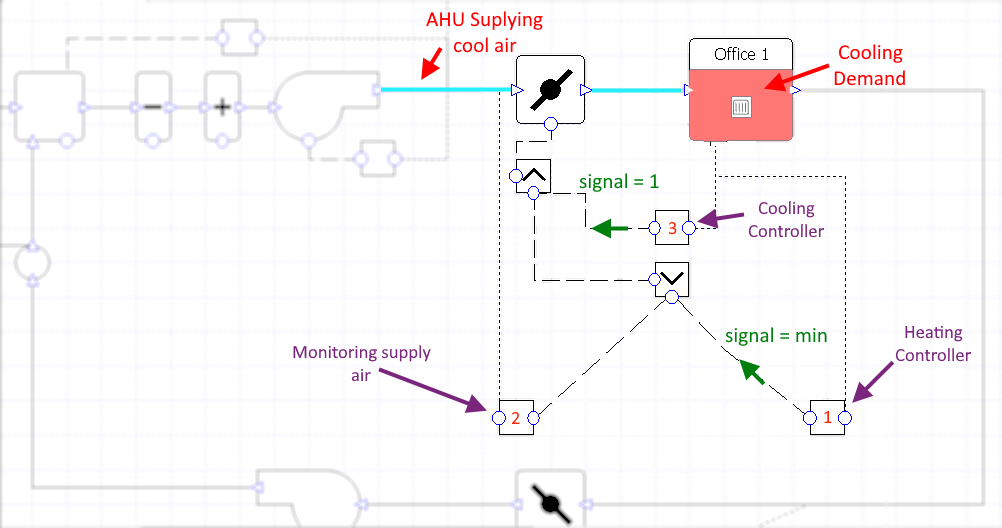
In the situation where one (or more) of the zone’s temperature goes above the temperature upper limit – 0.5°C , the heating controller of this zone will produce a signal of zero (as the bands do not overlap) while the cooling controller will produce a non-zero signal. This means that the Min controller connected to all heating controllers will pass a signal of zero onto the heating coil while the Max controller will pass the non-zero signal onto the cooling coil. This means that the supply air will be conditioned by the cooling coil to cool down this space. Other zones which may be cooled to below their heating setpoint will be warmed back up by their in space heating component. Please note that normally, there would be other measures involved to make sure this cool air doesn’t affect the temperature of the space too much, for instance a variable air flow rate where each zone can turn down the flow itself, as discussed in example 4.3.
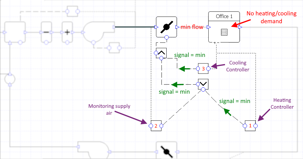
In the final situation, where all zones are within the thermostat limits and bands, all heating and cooling controllers will produce a signal of zero. This would mean that a signal of zero would be passed onto the coils by the Max and Min controllers and the supply air would not be conditioned.
Varying Flow Rate at the Damper
In this example, we want to model a variable air flow system with two central fans in an AHU where each zone can reduce the air flow rate down to a specified minimum flow rate if necessary.
This example follows on from the previous example, where it was mentioned that you can reduce the air flow to a zone that requires heating, but receives cold air due the central AHU trying to meet the cooling demand of another zone.
We want the air flow to be at its minimum level when the zone’s dry bulb temperature is between the upper and lower limit of the zone’s thermostat, so no superfluous conditioned air needs to be added to the space.
To summarise, the central AHU:
Provides cool air when at least one zone requires cooling, based on the zone with the highest cooling demand. This is because local space heaters prevent the other attached zones getting too cold.
If no zones require cooling, provides warm air to meet the lowest heating demand of one of the attached zones.
The AHU does not heat or cool if the temperature of all attached zones is within their upper & lower limits.
The dampers limiting supply to each zone:
If the AHU is supplying cool air and the space needs cooling, dampers should open.
If the AHU is supplying cool air and the space does not require cooling, dampers should close.
If the AHU is supplying warm air and the space requires heating, dampers should open.
Modelling in Systems
Varying the air flow rate a zone experiences in Tas Systems can be achieved by either opening/closing dampers or altering the speed of fans.
In our example, the fans will be in the central AHU and there will be dampers local to each zone after the air is split to be sent to each zone. Note that with this setup, not having the dampers would cause inconsistent design flow rate errors upon simulation.
Note
Controlling the fans in the central AHU is unsuitable for our desired control scheme. This is because controlling centralised fans, (changing their speed/pressure), affects the flow rate supplied to all zones simultaneously rather than individually.
To set up this control method will require 5 controllers. The first controller will be a controller set up to maximise the air flow rate when a zone requires heating. However, we want to be able to override this controller’s signal if the AHU is cooling the air. To do this, we need another controller which is reading the temperature of the supply air entering the zone.
This controller should send the minimum possible signal (Set by the Minimum Flow Rate field of the damper and corresponds to the damper allowing air into the zone at the minimum flow rate.) if the air has been cooled and a non-zero signal otherwise. Both of the above controllers should then be connected up to a Min controller.
Using the Min controller means we have the override. If the supply air has been cooled when the zone requires heating, the supply air controller will send the minimum signal to the Min controller. This will be eventually passed onto the damper which will restrict the air flow to the minimum flow rate. Similarly, if the supply air has not been cooled then the supply air controller will send a signal of 1, meaning that the heating controller’s signal will be the signal that decides the flow rate if the zone requires heating.
The purpose of the other two controllers is more clear cut. There is a controller set up to maximise the air flow rate when a zone requires cooling (As the AHU is prioritising cooling loads, the supply air will be cooled if requiring cooling).
Finally there will be a Max controller, reading the signals of the cooling controller and the Minimum controller. The Max controller will take the maximum of these two controllers and pass on this signal to the damper, which will accordingly proportion the air flow based on the signal.
The controller setup on the damper for varying the flow. It should be noted that the heating and cooling controllers attached to the zone have been deleted rather than unfocused in the figure. This is to aid the user’s understanding of the dampers controller’s setup.
Explanation
Heating Demand
The damper is open when the AHU supplies hot air and the zone has a heating demand.
When the zone has a heating demand and the AHU is supplying hot air, the heating controller will return a signal of one while the controller monitoring the supply air will also return a signal of one. This means the Min controller will pass onto the Max controller a signal of one, the maximum possible signal (The cooling controller would return the minimum signal, as the bands of the heating and cooling controller should not overlap).
This signal of one would be passed onto the Damper, which will allow the maximum flow rate of air into the zone. As the air has been heated, this will heat up the zone.
When the zone has a heating demand and the AHU is supplying cold air, the heating controller will return a signal of one while the controller monitoring the supply air will return the minimum possible signal.
Similarly the cooling controller will also return the minimum possible signal. With the control method set up, the heating controller and supply air monitoring controller would pass their signals onto the Min controller, which would take the minimum signal from the supply air controller. This signal would then be read by the Max controller, which would also read in the minimum signal from the cooling controller. As both controllers pass on the same minimum signal, the Max controller will pass this minimum signal onto the damper. Thus the damper will only allow the minimum amount of ventilation into the zone, stopping lots of cold air entering the zone as required.
Cooling Demand
The damper is open when the AHU supplies cool air and the zone has a cooling demand
When the zone has a cooling demand, the cooling controller will produce a signal of one. The heating controller, however, returns the minimum signal. This minimum signal when passed onto the Minimum controller will mean that the Max controller has to take the maximum of the minimal possible signal or the maximum possible signal. The max signal will thus be passed onto the damper, which will allow the maximum flow rate of air into the zone. As the air has been cooled, this will have a cooling effect on the zone.
No Demand
The damper is almost closed (min flow) when there is no heating or cooling demand, regardless of the AHU supply air temperature.
When there is no requirement for heating or cooling in the zone, both the heating and cooling controller will return the minimum signal. This will then mean that the Max controller will pass on the minimum possible signal to the zone and thus the damper will restrict the air flow down to the minimum flow rate.
Pressure Drops with Dampers
In this example, we are going to model a traditional VAV setup with varying terminal dampers and a static pressure supply fan.
As the previous examples deal with the setting up of the controllers for the AHU coils and varying terminal dampers, this example will only deal with how to set up the controllers on the fans, which are monitoring the pressure.
The static pressure supply fan will be pressurising the air to roughly 800 N/m2 and will work with the other components to ensure that the air in the zone is slightly pressurised, with a maximum pressure of around 5-10 N/m2.
Modelling in Systems
The setup required to produce the slightly pressurised air involves the use of pressure drops at the dampers and optimisers, along with two standard controllers, which are placed on the supply and extract fans.
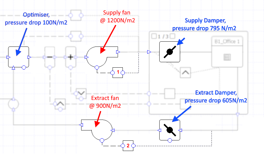
Figure 28 - The setup of the controllers for controlling the pressure around the circuit. The dampers have not been faded out in this image as they are causing the pressure drops.
The first thing we shall discuss is the setup of the Pressure and Pressure Drop fields of the components. We have two fans, a supply fan and an extract fan, which have fan pressures of 1200 N/m2 and 900 N/m2 respectively. The damper varying the flow rate before each zone, which is unique to each zone, will have a design pressure drop of 795 N/m2.
The extract damper, on the exhaust air of all zones, will have a design pressure drop of 605 N/m2.
Finally the optimiser, which is mixing fresh and re-circulated air together, will have a design pressure drop of 100 N/m2.
The first standard controller, on the supply fan, must ensure that the supply air after leaving the supply fan has a pressure of 800 – 805 N/m2 during all operational hours. Doing this should mean that the pressure the fan provides is fairly static for all flow rates. Also, it will mean that when the air flow rate is equal to the design flow rate the air will be supplied to the zone at around 5-10 N/m2, as the supply dampers before each zone all have a design pressure drop of 795 N/m2.
In this example, the design flow rate will be the maximum air flow rate. This means that when the supply dampers close, to reduce the flow rate, the damper will cause a pressure drop bigger than the design pressure drop. This means air flowing at the design flow rate will be at the maximum possible supply pressure.
The second controller is attached to the extract fan and is used to turn the fan down when the supply damper is closed. It is also used, in conjunction with the pressure drops and the supply fan’s controller, to keep the supply air slightly pressurised before being provided to the zone. The controller is using a sensor to sense the air pressure before the extract damper, and will tell the fan to turn up gradually as the pressure increases over 5 N/m2.
This set up, with the pressure drops and the controllers on the fans, will ensure that the air to the zone is slightly pressurised with a maximum pressure of 5-10 N/m2.
Supply Fan Controller
The controller connected to the supply fan, labelled 1 in Figure 28, is the controller ensuring the fan provides a pressure of between 800-805 N/m2 at all air flows. The controller is a Standard controller of Normal type, its sensor is on the duct immediately after the fan and the sensor is reading the duct’s pressure. The signal profile is set up as follows:
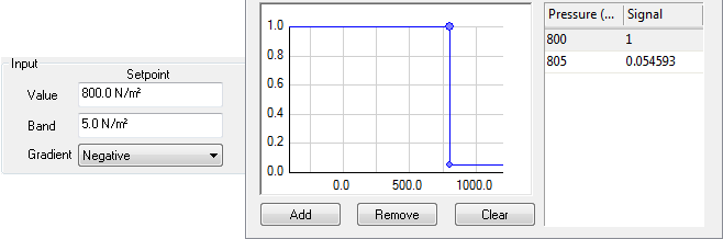
Figure 29 - The profile setup of the controller connected to the supply fan
The controller will produce a signal of 1 until the supply air’s pressure is at 800 N/m2. From this point, the signal will steadily decrease until at 805 N/m2 onwards it produces the minimum possible signal. This minimum possible signal will correspond to the minimum flow rate the fan can provide.
As we are varying the flow rate with dampers in this example, the minimum flow rate the fans can provide will be the sum of the minimum flow rate of each attached damper.
Extract Fan Controller
The controller labelled 2 in Figure 28 is the controller connected to the extract fan. This controller is a Standard controller of Normal type with its sensor placed before the extract damper. The sensor is reading the pressure of the air flowing through the duct. The controller’s signal profile is set as in Figure 30.
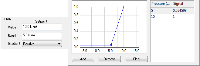
Figure 30- The profile setup of the controller connected to the extract fan
The controller will return the minimum signal when the air in this duct’s pressure is at or below 5 N/m2. This will steadily increase with pressures above 5 N/m2 until the pressure of the air is at or above 10 N/m2, where the controller will return a signal of one.
Explanation
The controller on the supply fan will ensure that, during all hours the fans operate, the air will be leaving the supply fan at a pressure between 800 – 805 N/m2 at all flow rates. Maintaining the air at this pressure will mean that when the supply damper closes to vary the flow rate, the supply fan will turn down to save energy rather than try to increase the pressure of the air flowing through it (i.e. a static pressure supply fan).
Also, when the air flow is at the design flow rate, which will be the maximum flow rate for this system, the air pressure of the air supplied to the zone will be between 5-10 N/m2.
As the pressure drop will be bigger at the supply damper for reduced air flows, the maximum pressure the supply air can take is between 5-10 N/m2, as required.
The second controller is also set up to turn the fan down to save energy. In this instance however, it will turn down when the air is only marginally pressurised and turn up gradually when the air pressure is 5 N/m2 running at maximum when the pressure is 10 N/m2.
The first controller will, along with the second controller and the pressure drops modelled by the dampers and optimisers, work to also make sure that the supply air is always slightly pressurised. This can be seen by checking the air pressure on the duct before the zone; the maximum value will be between 5-10 N/m2, while the minimum value will be zero (which occurs when the fans are turned off).