Standard Controllers - Basics
This subsection will deal with teaching the basics of creating standard controllers.
It will discuss:
What is a standard controller?
How do I create a controller?
How do I place the sensor
What does the controllers signal mean to each component?
Though these are the basics of a controller, a good understanding is important as an incorrect sensor placement can lead to a component not operating when needed.
What is a Standard Controller?
In TAS Systems, a controller is a device that produces a signal which the component will use to change its behaviour.
This means that, in effect, the controller is controlling the component- hence the name.
Unlike the other types of controllers, (mentioned in the section “Other & Chained Controllers”), the Standard controller produces its signal based on readings from any attached sensor(s).
A simple example of a Standard controller setup can be seen in Figure 1.
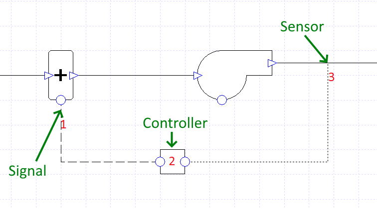
Figure 1 - The Basic setup of a controller. Label 1 indicates the controller’s connection to the component, label 2 indicates the controller while label 3 indicates the sensor
In Figure 1, the sensor at label 3 will take a reading from the duct directly after the fan.
This signal will then be passed to the controller at label 2, which converts this reading into a signal.
This signal is then passed from the controller to the component, where the component will act according to this signal.
With most Standard controllers, the signal will be a value between zero and one. However there is a type of Standard controller, the “Setpoint Passthrough”, that doesn’t operate in this manner. Please see Setpoint Tab: Properties Box for more information on the “Setpoint Passthrough” Standard controller.
The different types of Standard controller, along with the different variables the sensor can read and ways to generate the signal, (see Section “Standard Controllers - Properties”), make the standard controller a very powerful tool in TAS Systems.
Knowing how to correctly set up and use a standard controller is vital when setting up systems, especially complex ones, as one small mistake can cause issues with how your system works.
Creating & Connecting
To create a Standard controller in TAS Systems requires the use of a component that can be used in conjunction with a controller.
Such Components will have a circular port at the bottom of them which will have a red halo around it once the cursor is placed over it, like in Figure 2.
Figure 2- Click and drag on the circular port to create a controller
Once the user clicks and drags away from this circular port, a controller will be created. This controller will, by default, be connected to the component but the user can delete this connection if they wish by clicking on the connection and pressing the delete key on their keyboard (or by choosing delete from the right click contextual menu).
Upon deleting the connection the user will need to link the controller back up to another component or delete the controller before they are able to simulate their system.
To link a controller back up to a component, the user should click and drag from one of the circular ports on the controller until the newly created connection reaches the circular port at the component, or vice versa.
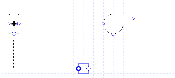
Figure 3 - To reconnect the connection between a controller and a component the user should click and drag from one of the two circular ports on the controller and place the connection over the circular port on the component.
Please note that the controller can be attached to multiple components at once, allowing for them to be controlled in the same manner.
To do this, the user will have to create connections from the controllers to the components, in the same manner as above.
Warning
Multiple components should not have more than one controller attached to it unless the controllers are operating on different day-types. See Section “Standard Controllers - Properties : Advanced Settings” for more on setting which day-types a controller operates on.
Sensor Placement Within the System
Sensor placement is an important matter in TAS Systems, as the reading from the sensor will be used by the Standard controller to produce a signal.
The sensor can only be placed in the following locations:
On the duct between two components
Onto a Zone component
Onto a plant room collection
It should be noted that the user can link multiple sensors from around their system back to a controller; in fact for one type of Standard controller it is necessary to have two sensors.
Even when more sensors are attached to the controller than needed, the user can choose which ones are used by the Standard controller by using the Sensor field within the properties dialog of the controller.
More about this Sensor field and the different types of Standard controllers can be found in :ref: ‘SetpointTabPropertiesBox’.
On the duct between two components
This means that the sensor takes the reading from the air passing through the duct.
To place a sensor here, click and drag from a circular port on a controller to create the sensor and then place the sensor over the appropriate duct.
Onto a Zone component
This means that the sensor takes the reading from the selected zone.
To place a sensor here, click and drag from a circular port on a controller to create a sensor and then place the sensor on the +/- symbol at the bottom of the component.
This will be highlighted in red, like in Figure 4.
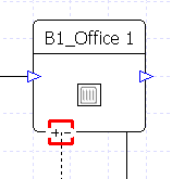
Figure 4 - A sensor being attached onto a zone component. The red square surrounding the +/- symbol indicates that the sensor is over the component and will be placed there if the user depresses the mouse.
Onto a plant room collection
This means that the sensor takes the reading from the attached plant room collection. To place a sensor here requires the same method as the Zone component, but placing the sensor on the +/- symbol of the collection.
The Signal’s Effect on the Controller
After the controller has passed on the signal to the component, the component will act according to the signal. How the component acts upon receiving the signal depends on the component.
As a general rule of thumb, the following is a rough guide on how the components will act.
Load Components
Load components are components which have a duty field.
With these components, the signal received by the component dictates the proportion of the component’s duty it will use to meet the demand.
As it is a proportion, a signal of zero will mean the component will not operate while a signal of one means that the component will operate using its full duty.
Fan and Pump Components
For the fan and pump components, a controller controls how much the component will increase the pressure of the medium flowing through it.
The signal received by the component dictates the proportion of the maximum pressure increase the component will increase the pressure to.
Please note that this maximum pressure increase is not the value entered in the component’s Pressure field. Instead the software will work the maximum pressure increase out by taking into account the Pressure field, along with the design flow rates and design pressure drops of components around the system.
Also, as pressure and flow rate are linked, controlling the pressure with a controller will also mean that the flow rate will vary.
How the signal affects the flow rate is shown using the equation below:
For the fan component, if the user wishes to set a minimum air flow rate, they could use the Minimum Flow Rate field of the fan.
To ensure that this minimum flow rate is met, TAS works out the signal the component requires to meet this flow rate and then sets it as the minimum signal of all attached controllers, ensuring the flow rate doesn’t drop below this level.
Damper and Valve Components
For the damper and valve components, the controller controls the capacity of the component, which will impact the flow rate and pressure of the system.
The signal the component receives dictates the proportion of the maximum capacity that the component will reduce to.
The maximum capacity is set in this case by either the Design Flow Rate field or the Capacity field of the component.
As the capacity of the damper or valve varies, so will the flow rate and pressure of the system.
For a damper, if the user wishes to set a minimum flow rate, they could use the Minimum Flow Rate field of this component. To ensure that this minimum flow rate is met, TAS works out the signal the component requires to meet this flow rate and then sets it as the minimum signal of all attached controllers, ensuring the flow rate doesn’t drop below this level.
Heat Exchangers and Optimisers
These components are normally used in conjunction with standard controllers of the “Setpoint Passthrough” type, please see :ref: ‘SetpointTabPropertiesBox’ for more.
With this option, the controller doesn’t produce a signal between zero and one but instead provides the reading the sensor has taken.
The component will then work by exchanging heat / mixing air to make the desired air-stream get as near to the reading as possible.
Standard Controllers - Properties
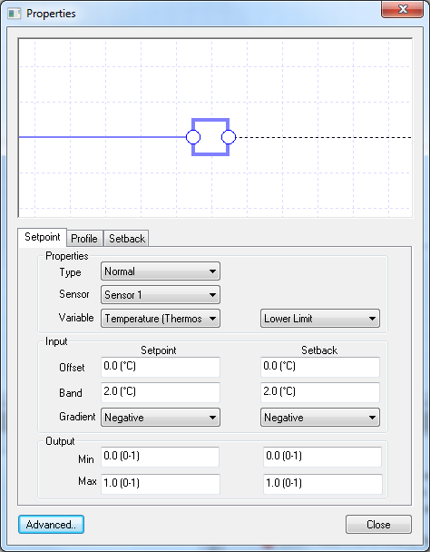
Figure 5 - The Properties dialog of the controller; the displayed tab is the Setpoint tab
The Standard controller’s properties dialog, with Figure 5 showing the Properties tab of the dialog, allows the user to set up how the controller works.
It is from these properties that the user will select what variable the sensor is reading, along with setting up how the signal is produced at the controller.
Making sure that your controllers are set up properly is of the utmost importance, as a minor mistake here can significantly change the signal produced at the controller. This could lead to components operating incorrectly and thus producing inaccurate results.
In the following subsections, the guide will talk through the various options available in the properties. It will start off by discussing the properties that affect how the controller manages its sensors and what reading the sensors take. It will then move on to how the controller converts the reading into a signal to be passed on to the component before finally moving onto some of the more advanced options of the Standard controller’s properties.
Setpoint Tab: Properties Box
Within the properties box in the Setpoint tab, are the three fields which detail how the controller manages the attached sensors. These are:
Type
Sensor
Variable
Type
The Type field of a standard controller allows the user to choose, from three options, how the controller manages the readings taken from the sensors. The options are:
Normal
Difference
Setpoint Passthrough
Normal
With the Normal option, the sensor reading is taken from the sensor and then used by the controller to produce the signal.
Please note if multiple sensors are attached to the controller, the controller will take the reading of the sensor chosen in the Sensor field.
Difference
With the Difference option, the controller takes readings from two sensors and subtracts one from the other. The difference between the two readings is then used by the controller to produce the signal.
Please note that it is required to have at least two sensors attached to the controller to use this option.
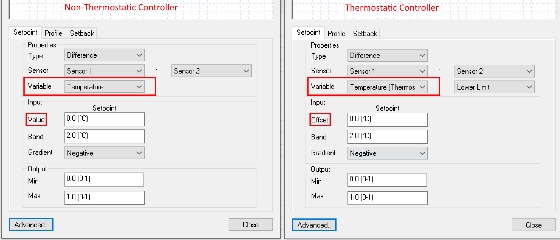
The Sensor field is used in this instance to decide what sensors are used and the order of subtraction. The minus sign in-between the two drop down menus, as pictured in Figure 6, indicates what sensor’s reading will be subtracted from the other:
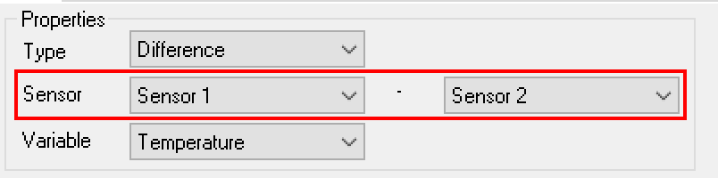
A screenshot illustrating the way you set the options for the difference controller. Please note the minus sign between the two sensor choices.
Setpoint Passthrough
A Standard controller of type Setpoint Passthrough can only be used with heat exchangers or optimisers. Any attempt to use this controller type with any other component will produce an error and you will not be able to simulate your system.
This type of controller works differently to all other types by not producing a signal between zero and one and also not using a profile to create the signal.
Instead, the controller takes the reading from the sensor and uses that as its signal. This signal is then passed onto the component, where it attempts to merge air streams /exchange heat to meet the signal reading. Often it will fall short of mixing to the signal reading, but will reduce the loads on components conditioning the air / fluid.
It should also be noted that the user will be able to set an offset when using this field, using the Offset field that appears. The offset can be positive or negative and will be applied to the sensor reading to offset the signal.
An example using a Standard controller of type Setpoint Passthrough can be seen in Example 5.1.
Sensor
For the Normal and Setpoint Passthrough types, the Sensor field allows the user to decide what sensor reading the controller will use, as these options don’t allow for multiple sensors to be used at once.
For the Difference type, please read the Difference paragraph of the Type property to see how the Sensor field is used.
It should be noted that any sensor attached to the controller and not displayed in the Sensor field will have its sensor readings disregarded.
Variable
The Variable field allows the user to choose what variable all of the sensors attached to the controller are sensing.
The available variables are broken up into two categories; Non-Thermostat variables and Thermostat variables. The difference between the two is a Standard controller using a Thermostat variable requires access to other parts of your model to create the signal, see :ref: ‘SetpointTabPropertiesBox’ for more.
The user is able to choose from the following variables:
Enthalpy
The Enthalpy option is a Non-Thermostat variable and is only available for controllers in air-side systems.
Upon choosing this option, the sensor will obtain the Enthalpy of the air in the duct or zone.
Flow
The Flow option is a Non-Thermostat variable and is available for controllers in both plant room and air-side systems.
When this option is chosen in an air-side system, the sensor will read the flow rate of the air in a duct or zone.
When this option is chosen in a plant room system, the sensor will read the fluid flow rate from a duct.
Humidity Ratio
The Humidity Ratio option is a Non-Thermostat variable and is only available for controllers in air-side systems.
Upon choosing this option, the sensor will obtain the Humidity Ratio of the air in a duct or zone.
Load
The Load option is a Non-Thermostat variable and is only available for controllers in plant room systems.
Upon choosing this option, the sensor will read the load (which in the collection’s result section is stated as “demand”) from the attached collection.
Please note that if you attach the sensor to a duct, the load value read by the sensor will be zero as the duct does not have a load. This will mean that your component will not operate.
Pollutant
The Pollutant option is a Non-Thermostat variable and is only available for controllers in air-side systems.
Upon choosing this option, the sensor will obtain the pollutant reading of the air from either a duct or a zone.
Pressure
The Pressure option is a Non-Thermostat variable and is available for controllers in both plant room and air-side systems.
Upon choosing this option for an air-side system, the sensor will read the air pressure from the attached duct or zone.
When used in a plant room system, the sensor will read the pressure of the fluid in the duct or collection.
Relative Humidity
The Relative Humidity option is a Non-Thermostat variable and is only available for controllers in air-side systems.
Upon choosing this option, the sensor will read the relative humidity of the air in a duct or zone.
Relative Humidity (Humidistat)
The Relative Humidity (Humidistat) option is a Thermostat variable and is only available for controllers in air-side systems.
When using this option, the sensor will read the relative humidity of the air in the zone.
Please note that when using this option you cannot attach the sensor to a duct, as it will produce an error, unless it is the duct immediately after the zone.
This error occurs because the controller uses the zone’s humidistat, set in the zone’s internal condition, to produce the signal. To help TAS identify which zone’s humidistat it should be using during this process, the sensor must be attached to the zone or to the duct immediately after the zone.
There is more information about how the humidistat limits are used to produce the signal in Signal Fields: Standard, Thermostat.
Temperature
The Temperature option is a Non-Thermostat variable and is available for controllers in both plant room and air-side systems.
When used in an air-side system, the sensor will read the dry bulb temperature of the air in a duct or zone. When used in a plant room system, the sensor will read the temperature of the fluid from a duct or a collection.
Temperature (Thermostat)
The Temperature (Thermostat) option is a Thermostat variable and is only available for controllers in air-side systems.
When using this option, the sensor will read the dry bulb temperature of the air in the zone.
Please note that when using this option you cannot attach the sensor to a duct, as it will produce an error, unless it is the duct immediately after the zone.
This error occurs because the controller uses the zone’s thermostat, set in the zone’s internal condition, to produce the signal. To help TAS identify which zone’s thermostat it should be using during this process, the sensor must be attached to the zone or to the duct immediately after the zone.
There is more information about how the thermostat limits are used to produce the signal in Signal Fields: Standard, Thermostat.
Wetbulb
The Wetbulb option is a Non-Thermostat variable and is only available for controllers in air-side systems.
Upon choosing this option, the sensor will read the wet bulb temperature of the air in the duct or zone.
Min Fresh Air
The Min Fresh Air option is a Thermostat variable and is only available for controllers in air-side systems.
Upon choosing this option, the sensor will read the flow rate of air through the zone.
Please note that when using this option you cannot attach the sensor to a duct, as it will produce an error, unless it is the duct immediately after the zone.
This error occurs because the controller uses the zone component’s Fresh Air Rate field to produce the signal. To help TAS identify which zone’s Fresh Air Rate field it should be using during this process, the sensor must be attached to the zone or the duct immediately after the zone.
Please note that unlike other Thermostat variables, you do not get to choose a Thermostat limit with this option, as discussed in Signal Fields: Standard, Thermostat.
Creating the Signal
Once the controller has managed its sensor readings, it must then convert the produced value into a signal for the component.
In TAS Systems, the user will need to detail how this conversion process will work by creating a profile the controller can refer to when creating the signal.
As this profile will be based on the variable the sensor has read, the user should note that the options for creating this profile will depend on if the user chose a Thermostat variable or a Non-Thermostat variable in the Variable field of the controller’s properties.
In this sub-section, the guide will explain the process for Non-Thermostat variables. The next sub-section will describe how the signal is created for Thermostat Variables.
Controllers that use a Non-Thermostat variable are called Non-Thermostat Standard controllers, while controllers that use a Thermostat variable are called Thermostat Standard controllers.
Signal Fields: Standard, Non-Thermostat
With Non-Thermostat Standard controllers, the user can create the profile by inputting the data into the fields contained within the Input box or by going straight to the Profile tab and creating the profile there.
If the user chooses to use the fields in the Input box, a simple profile will be created based on the variable the sensor is reading. This simple profile will only change once from the maximum possible signal (1 by default) to the minimum possible signal (0 by default), or vice versa, over a set band where it varies linearly.
There are three fields which help to create this profile:
Band
Gradient
Value
Before giving an example of using these input fields, it should be noted that the profile created by these inputs will be visible in the Profile tab.
It is strongly recommended that the user checks this profile to make sure that they have set the profile up correctly.
Band
The Band field of the controller allows the user to enter a proportional band into the controller.
This proportional band details the period (in the units of the variable the sensor is reading) that the profile takes to go from the maximum signal of 1 to the minimum signal of 0, or vice versa.
Please note that this band between the two values will be linear.
Gradient
The Gradient field allows the user to decide, in their simple profile, whether the proportional band in their profile has a positive or negative linear gradient.
If the user chooses the positive option, the profile will start off at the minimum signal of 0 before increasing throughout the proportional band to the maximum signal of 1.
Likewise if the user chooses the negative option, the profile will start off at the maximum signal of 1 before decreasing throughout the proportional band to the minimum signal of 0.
Value
The meaning of the Value field will depend on the user’s choice in the Gradient field.
If the user chooses the positive option in the Gradient field, the Value field requires the user to enter a value such that if the controller has a reading bigger than or equal to this value, it will return a signal of 1.
Similarly if the user chooses the negative option in the Gradient field, the Value field requires the user to enter a value such that if the controller has a reading smaller than or equal to this value, the controller will produce a signal of 1.
Example
We will now work through an example of how this profile is set up in practice using these fields.
Let’s say that we have a cooling coil which we want to start cooling the air passing through it when a zone’s temperature is at 23°C. We also want the coil to cool using its full duty when the zone is at a temperature of 24 °C and above.
In this example, we would create a Standard controller from the cooling coil with the sensor attached to the zone. The Standard controller would be of Normal type while the variable the sensor is reading would be temperature.
In the Input box, the user would enter the following details to create the profile:
Band - 1°C
Gradient - Positive
Value - 24°C
This will produce the required control strategy, which can be seen by looking at the profile on the Profile tab:
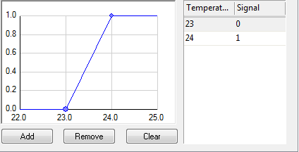
Figure 7 - The profile of the controller, via the profile tab
Using Figure 7, we can see how this profile works.
When the air temperature in the zone is below 23 °C, the sensor will read this and pass on this reading to the controller. The Controller will then compare it against this profile and send a signal of zero to the cooling coil, meaning the coil will not operate.
For a temperature reading between 23°C and 24°C, the controller will read off the signal based on the temperature and pass the signal onto the cooling coil. The coil will then proportion the amount of duty it will provide to meet the load according to this signal.
When the temperature reading at the zone is at 24°C or above, the controller will send a signal of 1 to the cooling coil; this will mean that the cooling coil will work at full capacity.
More examples of creating a signal profile with a non-thermostat standard controller can be found in the section “Examples”.
As mentioned before, another way of creating the profile is to go to the Profile tab directly and create it from there.
The user can add points to the profile in two ways, by either clicking directly on the profile or by clicking the add button.
Upon creating a point the user can edit its position by clicking and dragging it on the profile to the desired position or by editing the points on the table beside the profile graph.
For more information on creating the profile for the controller the user can watch the “Systems and Collections - Controls – Profile” video in the TAS Systems User Guide.
Note
You can access the Type, Variable and Sensor fields from the Profile tab. Any changes made on this tab will overwrite the inputs on the Setpoint tab and vice versa.
Signal Fields: Standard, Thermostat
Now we shall discuss how to create the profile when using Thermostat Standard controllers.
With a Thermostat Standard Controller, the profile created by TAS will use the thermostat or humidistat of the zone, set in the zone’s internal condition, or the Fresh Air Rate field in the zone component’s properties. This is done so users can easily set up their controllers to control to data already entered into the software.
The first big difference between the Thermostat controllers and the Non-Thermostat controllers is that the user must use the fields in the Input box to create the profile.
While users will be able to view their profiles and edit the maximum and minimum signal from the profile, the profile itself must be created using the Input fields.
The first thing to do when creating the profile linked to the thermostat or humidistat is to decide on which limit you will use to produce the profile. The user can choose from the following options from the drop down menu that appears next to the Variable field:
Lower Limit
Upper Limit
Lower and Upper Limit
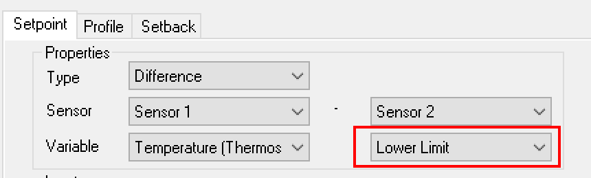
Figure 8 - Figure showing the additional option that appears when a thermostat option is chosen
Please note that when using the Min Fresh Air variable you will not be given an option of what limit to create the profile from. This is because the Min Fresh Air variable will always create the profile from the Fresh Air Rate field of the Zone component.
Lower Limit
Using this option will mean that the lower limit of the thermostat/humidistat will be used to generate the profile for generating the signal.
An example of when you could use this option would be for controllers connected to heating components.
Upper Limit
Using this option will mean that the upper limit of the thermostat/humidistat will be used to generate the profile for generating the signal.
An example of when you could use this option would be for controllers connected to cooling components.
Lower and Upper Limit
Using this option will mean that the lower and upper limit of the thermostat/humidistat will be used to generate the profile for generating the signal.
It should be noted that this option will generate a profile different to the others as it is generated using the upper and lower limit values along with two associated bands, rather than just the one value and band. The differences this causes will be discussed later on in this subsection, followed by an example.
One example of when you could use this option would be to control the fans so that when the temperature of the zone is within the thermostat limits the fans won’t operate to provide the zone with conditioned air.
The thermostat/humidistat limit chosen, or the Fresh Air Rate of the zone component, will act in the profile in much the same way as the Value field does for Non-Thermostat controllers. Due to this, the user will not find a Value field in the Input box. With a Thermostat Standard controller, the Input box contains the following fields:
Band
Gradient
Offset
Band
The Band field works in mostly the same way as with Non-Thermostat controllers.
The one major difference is the case where the profile is generated using both the lower and upper limits of a thermostat/humidistat. In this instance two bands will be created on the profile, with one for the profile’s change at the upper limit and one for the profile’s change at the lower limit.
It should be noted that the user can enter a band value into the controller such that the two proportional bands from the lower and upper limits will intersect rather than reach the minimum signal of zero.
When this happens, the profile will only be able to set the minimum at the intersection point of the two bands. This minimum will produce a signal bigger than 0 (and possibly bigger than a minimum value set in the Minimum field, please see Output: Maximum and Minimum Values), so it is strongly recommended that the user only enters a band value which does not lead to the two proportional bands intersecting.
Gradient
The Gradient field works in the same way as with Non-Thermostat controllers, although the user should be wary when using both the lower and upper limit of a thermostat/humidistat to create the profile as there will be two slopes sloping in opposite directions.
In this case the choice of gradient applies to the slope starting at the lower limit. This means the “Positive” option will have the signal at max within the limits, while the “Negative” option has the signal at max outside of the limits.
Offset
The Offset field allows the user to offset their created profile by the value entered here. The user can enter a positive or negative value here, allowing them to offset the profile away from the data used to create the profile.
When a positive value is entered, all points on the profile will be offset in the positive direction by the amount stated in the offset field, while a negative value would mean that all points are offset in the negative direction.
After the user generates the profile using these options, it is recommended they go to the Profile tab to check the profile is created as they would have expected.
Example
We will now work through an example of how this profile is set up in practice using these fields.
Let’s take the situation where we want to set up our fans, servicing only one zone, so that they only create an air flow when the zone’s air temperature is outside of the lower and upper limit of the zone’s thermostat.
The air provided to the zone will be conditioned (We will not discuss setting up the controllers to condition the air appropriately here, just the controller connected to the fans. An example of how to set up controllers to condition the air is given in Example 5.2.) to warm or cool the zone to be within the thermostat limits.
During hours where the zone’s air temperature is inside the thermostat limits, we want the fans to gradually turn off so that no ventilation is provided. We will assume that the difference between the upper limit and lower limit is 4°C, meaning that entering a band value smaller than 2°C will mean the two bands do not intersect.
To set this scenario up, the user would create a controller connected to the fans. A sensor would then be attached to the zone component. In the controller’s properties, the Type field would be set to “Normal” while the Variable field would be set to “Temperature (Thermostat)”.
In the Input Box, the user would enter:
Band - 0.5°C
Gradient - negative
Offset - 0°C
This will produce the required control strategy, which can be seen by looking at the profile in Figure 9:
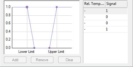
Figure 9 - The controllers signal profile, from the profile tab.
From the profile we can see that when the air temperature is below the lower limit, or above the upper limit, the controller will send a signal of one to the fans. A signal of one means the fans will provide the maximum flow rate to the zone.
Between the thermostat limits the two slopes indicate the fan reducing / increasing the flow rate in correspondence with the temperature of the zone.
At the bottom of the slopes the controller will send a signal of zero to the controller. This will tell the fans to not produce any flow at all.
The user will find more examples of Thermostat Standard controllers in the section “Examples”.
From the profile page the user can edit the signal produced at each point, for instance in the example above they could enter a signal between zero and one to replace the zero signal as the minimum signal. This would represent a situation where the fans have to provide a minimum amount of air to each zone.
Although it can be done from here the user would normally use the Minimum Design Source Field of the fan to set this minimum signal.
Output: Maximum and Minimum Values
The Min and Max fields in the Output box allow the user to hand select the minimum and maximum signal a controller will be able to send:
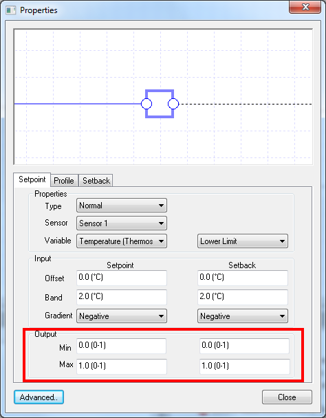
Figure 10 - The Minimum and Maximum fields of the controller
This means that instead of editing a profile, the user can enter the minimum and maximum values a controller can send and the profile will be altered to take this into account.
It should be noted that fields from certain components, i.e. the Minimum Flow Source field from flow components, have the ability to override any value set in the Min field. This is because these fields work by setting the Minimum signal to alter how the component works.
In the case of the Minimum Flow Source field of a flow component, the Minimum Flow Rate through the component is set by working out the signal that will cause this flow rate at the flow component and then setting this as the minimum value the profile can take. To ensure that this minimum flow is met, the component will override any minimum signal set in the controller.
It is recommended that the user checks that they have not set the Min and Max signal to the same value. When this happens the controller will always produce the same signal, as the profile will be equal to the same value at all points.
Setback Tab and Setback Values
When the user first goes to the Setback tab, all they will find is a Schedule field with a drop down menu for options.
The Schedule field allows the user to apply one of the schedules in their system file to the controller to detail its main hours of operation. Upon choosing the schedule, the user will then have to set up how the signal will be produced during out of scheduled hours, also known as setback hours.
The setback option works just like the setback option in the building simulator. The user will set up the profile in the same way as discussed before, but the profile will appear on the Setback tab. The required fields to produce the Setback profile in the input box will appear in the space on the right hand side of the box.
Advanced Settings
The Advanced settings of a controller allow the user to modify how the controller works. As these are the advanced settings, the user will rarely need to modify the entries kept in this dialog.
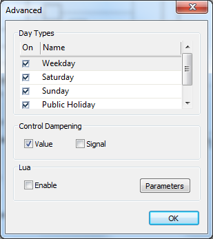
Figure 11 - The advanced options dialog for the standard controller
The three main settings the user can edit from here are:
Day types
Control Dampening
Lua Code
Day Types
This field allows the user to choose what day types the controller will send a signal to the component.
Listed in the box is a list of all day types from the calendar in the Building Simulator file. The user is then able to check the day types they wish the controller to send the signal on, while unchecking the days they wish no signal to be sent.
This will mean that the component will not operate on this day type, unless another controller is attached to this component which is sending a signal on this day type.
It should be noted that only one controller on any given day type should be sending a signal to the component. Multiple signals being sent on the same day type will lead to the component not acting how the user would expect.
Please note that the results of the controller will display a signal of zero for all hours on the days the controller is not operating.
Control Dampening
The calculation of results in TAS Systems is an iterative process, as a change in one component will cause knock on effects all around the system. Due to this iterative process, systems will converge onto an answer to give as a result in this hour.
The Control Dampening options allow the user to decide if they wish to use dampening on the sensor and signal calculations. This process should reduce fluctuations in the calculations and converge on a result more quickly.
In this field the user is presented with two tick box options for value and signal. Ticking the Value option means that the sensor reading calculations will have dampening to reduce the fluctuations while ticking the Signal option will use dampening with the signal calculations.
By default only the Value tick box is ticked.
Lua Code
LUA code is an advanced feature which allows the user to enter LUA code into the software to describe how the controller should work.
When enabling this option, by ticking the enable tick box, the user will be presented with a Code tab where the user can enter their own LUA code to set how their controllers work.
Alongside the enable tick box is a parameters button. This allows the user to set which options appear in the Properties tab when LUA code is enabled. The user should note that this is an advanced feature which may cause problems. If the user decides to use this feature they should save often and keep backups.
As LUA code will not be used by most users, we will not discuss it any further in this guide.