Other & Chained Controllers
In the previous sections we have discussed how to set up a standard controller using sensors; however the Standard controller isn’t the only controller available to use in TAS Systems.
There are 5 other types of controller to use which all share one thing in common; they use signals created by other controllers as their input to produce a signal of their own, rather than using a sensor reading to produce a signal.
This section will at first talk through how to create these new controllers in TAS Systems. It will then go through and explain each type of controller and give a quick example of when to use each one.
Creating & Chaining
To create one of these new controllers requires the user to have already created a Standard controller, but to have not yet connected a sensor to it.
Without the sensor connected, the user will note that there is an additional circular port at the bottom of the standard controller. It is by using this port that the user creates the new controllers.
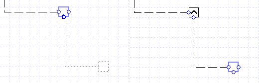
Figure 13 - On the left, the new controller being set up by using the additional port at the bottom. On the right, is the finished controller setup. The original controller is the one that transforms into one of the newer types, not the created one chained to this controller.
To create the new type of controller, the user will need to click and drag on the circular port at the bottom of the controller. This will create a new Standard controller connected to the original controller, which will now have a symbol in it.
This is because the original controller has been converted from a standard controller into one of the new types of controller, and the symbol indicates what type of controller it is.
It should be noted that any type of controller can be attached to these new types of controllers; all controllers that are attached are referred to as chained controllers.
Upon clicking on the controller with the symbol to open up the properties, the user will see the four available properties.
Along with Name, Description and Day Type fields (which works in the same way as the Standard controller’s Day Type field) there is a Type field. The user has five choices in this Type field, which will change the method of how the controller produces its signal.
These five choices will be discussed in the next subsection.
New Controller Types
The five types of new controller all operate in different ways. This subchapter will explain how they all work:
Maximum Controller
Minimum Controller
Not Controller
If Controller
Sig Controller
Maximum Controller
The Maximum controller is represented on the schematic by a controller with an upwards pointing arrowhead symbol:
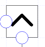
Figure 14 - The Maximum Controller
As a controller, it takes signals from all controllers chained to it and works out the maximum signal of all these signals. It then uses this maximum as the signal it passes on.
It should be noted that a Max controller requires all the signals it receives to be of the same type. So, for instance, you cannot send a signal from a Passthrough controller and a signal from a standard (0-1) controller to the same Max controller.
An example of using this controller can be found in the section “Examples: AHU Heating and Cooling Setup”.
Minimum Controller
The Minimum controller is represented on the schematic by a controller with a downwards pointing arrowhead symbol:
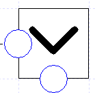
Figure 15 - The Minimum Controller
The Minimum controller is represented on the schematic by a controller with a downwards pointing arrowhead symbol.
As a controller, it takes the signals from all controllers chained to it and works out the minimum signal from them. It then uses this minimum signal as the signal it passes on.
It should be noted that a Min controller requires all the signals it receives to be of the same type. So, for instance, you cannot send a signal from a Passthrough controller and a signal from a standard (0-1) controller to the same Min controller.
An example of using this controller can be found in the section “Examples: AHU Heating and Cooling Setup”.
Not Controller
The Not controller is represented on the schematic by a controller with the logical negation symbol:
The Not Controller
Unlike the Max and Min controllers, it can only have one chained controller connected to it.
It works in much the same manner as a not gate in logic, meaning that if the chained controller sends a signal of 1, the not controller will return a signal of zero, and vice versa.
Unlike in logic, however, the signal the not controller receives will not always be one or zero. Hence the Not controller returns a signal of:
This is for all signals sent by the chained controller.
If Controller
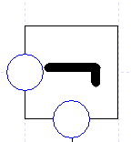
The If controller is represented on the schematic by a controller with an IF symbol and allows the user to set up a control system using if statement logic:
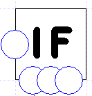
Figure 17 - The If Controller
The If controller requires precisely 3 controllers to be chained to it. Each of the chained controllers must be uniquely connected to the three ports at the bottom of the controller. If more than one controller is chained to one of these ports, the software will inform you of this in the error section and you will not be able to simulate your system.
The If controller works in the following manner. The controller chained to the first port of the If controller (the left port) is the condition controller.
When the condition controller sends a signal of 1 to the If controller, the If controller will return the signal of the controller chained to the second (middle) port.
When the condition controller returns a signal of zero, the If controller will then return the signal of the controller chained to the third (right) port.
In the situation where the condition controller sends a signal between zero and one, the If controller will return the following signal:
Where \(S_1\) is the signal of the condition (left port) controller, \(S_2\) is the signal of the second chained (middle port) controller and \(S_3\) is the signal of the third chained (right port) controller.
There are a couple of considerations to bear in mind when using the If controller:
If you want the If controller just to return the signals from the second and third chained controllers, then the first controller must be set up to do so. This will mean setting up the condition controller to either have a very small band or a band equal to zero. However it should be noted that using a very small or zero band may end up with the results failing to converge, unless the reading the condition controller is using is constant for the hour (i.e. reading the temperature of the fresh air).
When using Standard controllers for the second and third chained controllers, the controllers must be sending signals of the same type; i.e. you cannot send signals from a Setpoint Passthrough controller and a standard (0-1) controller. If the standard controllers are not using the same type, then an error will be produced and the user will not be able to simulate their system.
Sig Controller
The Sig controller is represented on the schematic by a controller with a graphical signal profile on it:
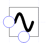
The Sig Controller
Like the Standard controller, the Sig controller creates a signal to pass onto the component from a signal profile. However, unlike the Standard controller, this signal is not created by sensors attached to the controller but by the signal sent to it by a chained controller.
It should be noted that the Sig controller can only have one chained controller connected to it.
When using the Sig controller, the user will need to create the signal profile in the same way as discussed in the section Signal Fields: Standard, Non-Thermostat.