Multiplicity
A number of entities in Tas Systems can have a multiplicity value. The meaning of this term varies slightly depending on the context.
The following entities can have multiplicity factors:
Airside systems
Airside groups
Multi-Chillers, Multi-Boilers
Renewables (solar, PV, wind)
Generally, multiplicity has the effect of representing multiple instances of the item it is applied to. In the case of airside systems, for example, a multiplicity of 5 would increase the consumption of that airside system by 5 times. In the case of a PV panel, a value of 7 would result in 7 times the amount of renewable power generation.
When used in the context of airside groups, multiplicity represents the number of times the grouped items are present. When a zone component is part of the group, however, 1 distinct zone can be applied per zone component in the group.
Airside Systems
Airside systems can have a multiplicity by selecting the airside system and looking at the properties window:
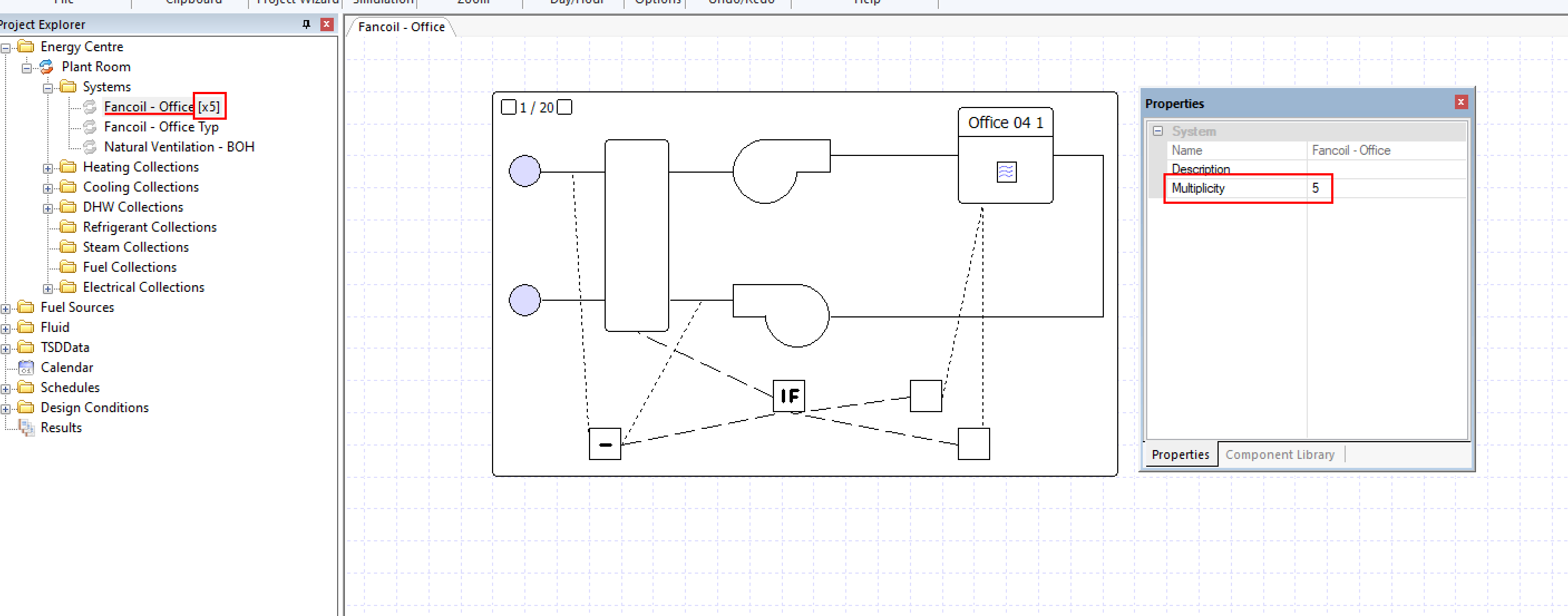
When an airside system has a multiplicity, the factor the airside system is multiplied by appears next to the airside system name in the treeview.
An airside system with a multiplicity increases the consumption of that airside system by that value.
This is often useful when you are modelling a large building with a lot of repetition and thermally identical zones. Rather than modelling every single zone and every single surface, a smaller number of representative zones can be modelled with multiplicity factor applied in order to produce a smaller model that will simulate faster.
Airside Groups
Groups in the airside system schematics can have a multiplicity that represents multiple occurrences of the components contained within that group.
For example, consider the following simple airside system that doesn’t serve any zones:
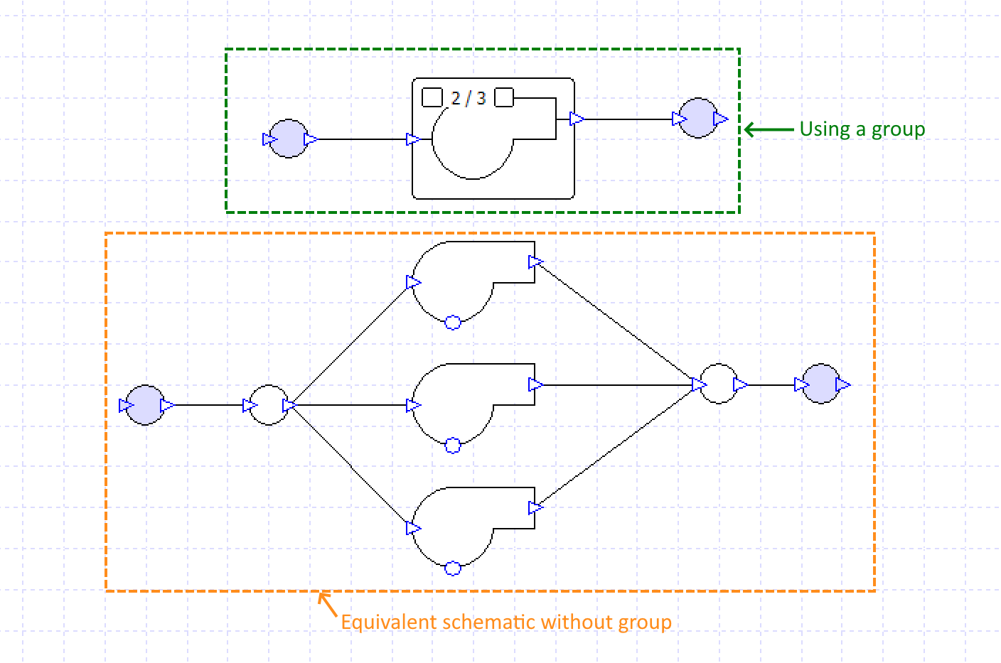
In this schematic, both airside systems are equivalent but in the topmost schematic, the 3 fans have been represented with 1 fan in a group with a multiplicity of 3.
This saves the need to setup the fan properties for each fan individually, and simplifies the appearance of schematics where there is much repetition.
You can also include zone components in a group that has multiplicity and still assign unique zones to each of the zone components in that group:
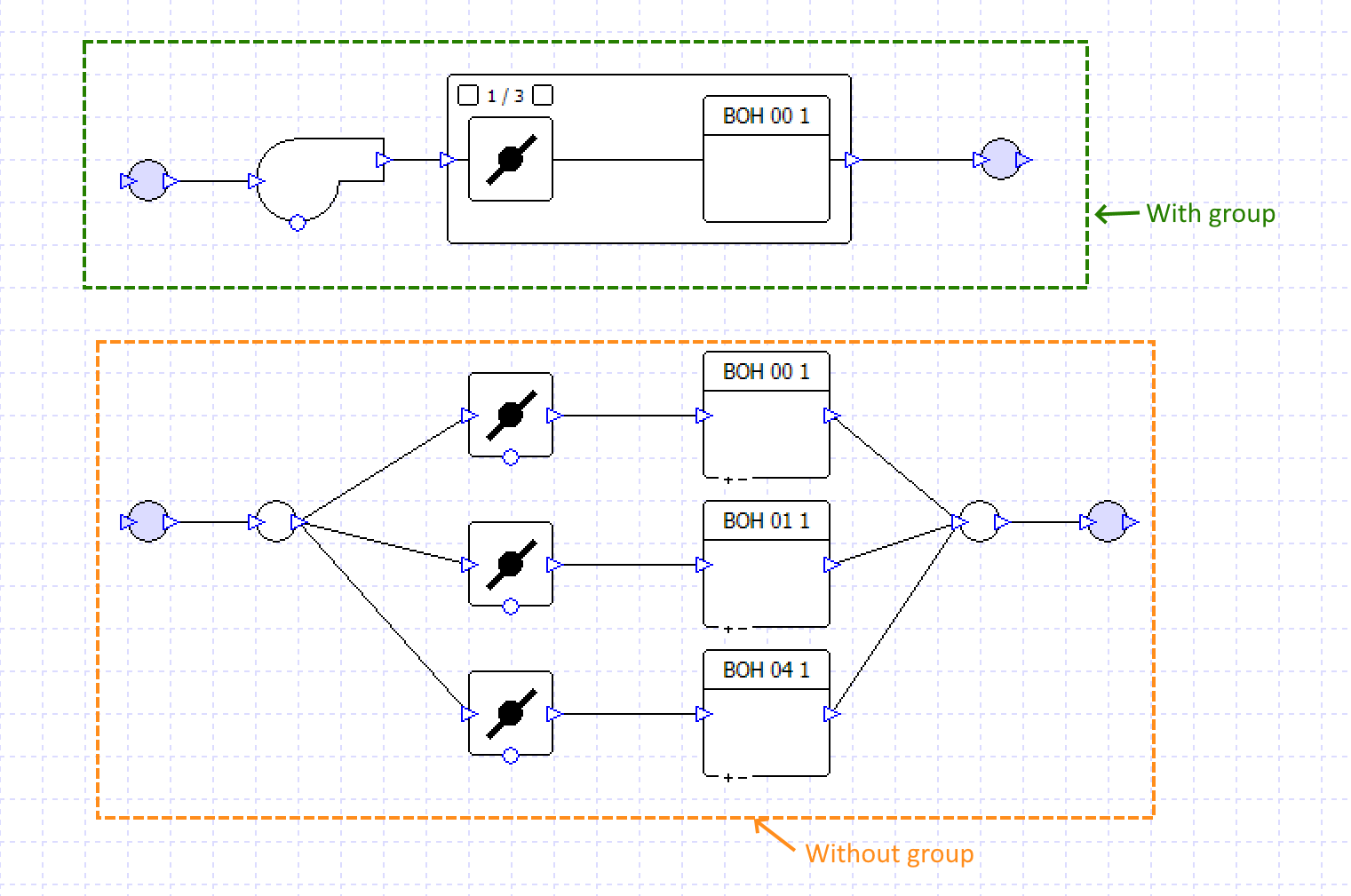
For more information about creating groups containing zone components, see Zone Components & Groups.
Multi-Chillers & Multi-Boilers
Multi-Chillers and Multi-boilers can have a multiplicity:
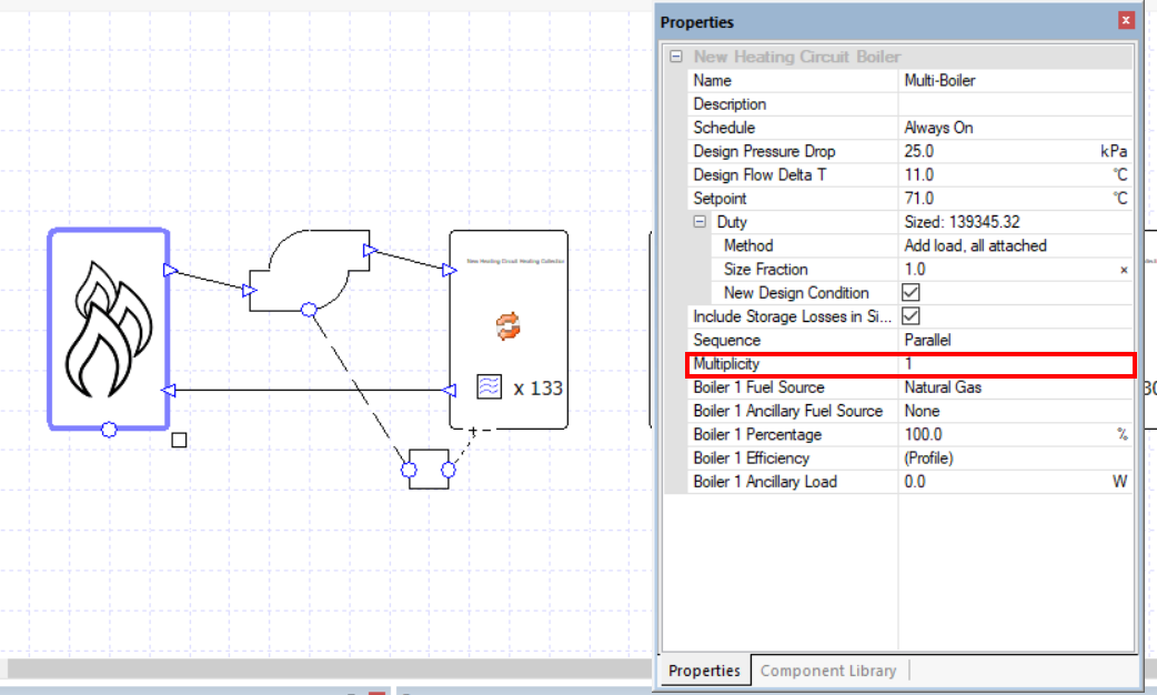
This field represents the number of boilers or chillers that this component represents, which can then be configured in series/parallel.
For more information about these components, see their respective sections in the component guide.
Renewables
Components used to model renewables such as PV, solar hot water panels and wind turbines can have a multiplicity that represents the number of these components present.
If, for example, you are modelling 5 PV panels each with an area of 2 square meters, you can use a multiplicity of 5 and an area of 2 and use a single PV panel component rather than 1 with an equivalent area of 10 square meters or 5 individual PV panel components.
For more information, see the component guide for each of these components.