Airside Systems
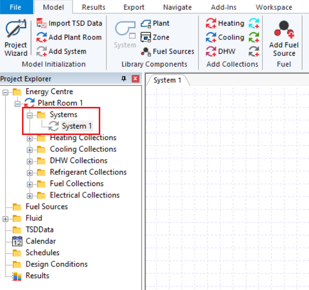
As explained when we introduced plant rooms, Airside Systems are contained within the Systems folder:
As the name implies, airside systems concern the flow of air.
In the case of natural ventilation, there is no mechanical ventilation system.
For mechanical systems such as fancoil systems, air is introduced from outside and may be passed to components which condition the air via ducts. Once the air has been conditioned, the air is then usually passed to the zone via ducts.
Air is also often extracted from zones via ducts, to avoid creating high pressure rooms and also to recover heat from exhausted air via heat recovery units.
Pressure
In order for air to flow through ducts, it needs to be pushed. This this pushing force, or pressure, is usually provided by fans.
When fans spin, their blades exert positive pressure on the adjacent air in front of the fan, and negative pressure on the air behind the fan.
The amount of pressure that is required to make air flow around the ducts depends on the number and nature of the components connected to those ducts, as well as the length and width of the ducts themselves.
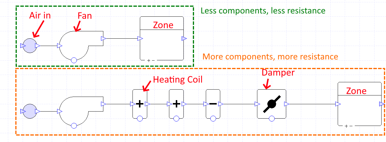
Heating and cooling coils contain an element that is either very hot or very cold. They heat air and cool air when the air molecules bump into the element, so the more collisions there are, the more effectively the heat is transferred.
As the coil works by blocking the path of the air (to maximise collisions), the coil has a high resistance. As a result, the fans need to provide more pressure to allow the same volume of air to pass compared to a pathway without a coil.
When designing an airside system, it is therefore important to make sure your fans can exert enough pressure on the air in order to achieve the desired flow rate through the system.
Specific Fan Power
Specific fan power, pressure and the efficiency of a fan are related:
Where \(\text{Pressure}\) is in \(n/m^2\) and \(\text{SFP}\) is in \(W/l/s\).
This is useful to remember, as manufacturers often specify the fan SFP and in Tas Systems, we specify the fan pressure.
Creating
To create an airside system, drag components from the component library onto an airside schematic:
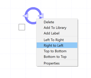
The direction of components can be reversed by right clicking on them:
Components can be joined together by linking the duct nodes:
Note how additional nodes can be added by clicking on the ducts and dragging. These are purely for display purposes, and can be removed by clicking on them and pressing delete on the keyboard.
This very simple airside system just contains an inlet and an outlet, and a fan to move air between the two. It does not serve any zones.
In order to complete this airside system, we need to specify the properties of the fan. We can do this via either the properties panel, or by double clicking on the fan:
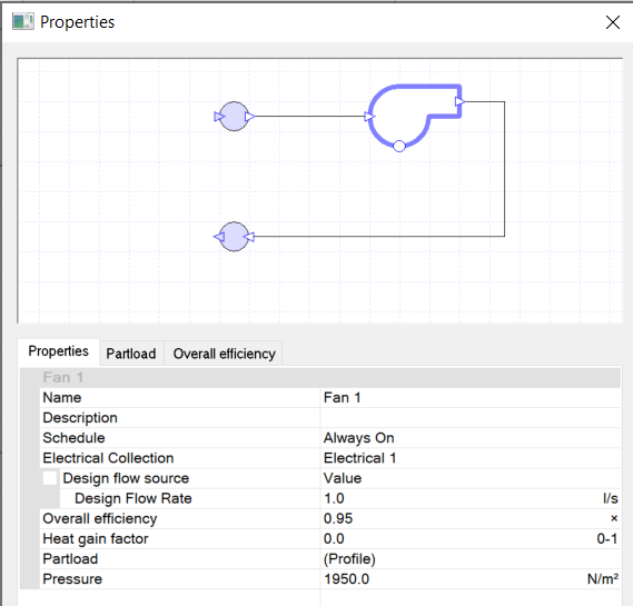
In this example, we can use a flow rate of \(1 l/s\), an overall efficiency of 95% (0.95) and a pressure of \(1950 n/m^2\).
Remembering Pressure-SFP relation, the SFP of this fan is:
By default, the fan has been assigned to the default Electrical collection.
This fan will be modelled as always on, but could be controlled via a schedule or a controller (see the Controller Guide section for more).
For a full description of the properties of any component, see the component guide section of this manual.
This simple airside-system can now be simulated, and results viewed by clicking on the components & ducts in the schematic.
Zone Components & Groups
The zone component features in almost every air-side system schematic, as it is used to represent the zones which are served by that airside system.
The airside zone component can have components within it such as radiators and DX coils. These components are components that are local to the zone itself.
To add a zone to a zone component, drag a zone from the TSD data onto the zone component:
You can also add multiple zones to a zone component by grouping it. Select the zone component and press the group button in the ribbon:
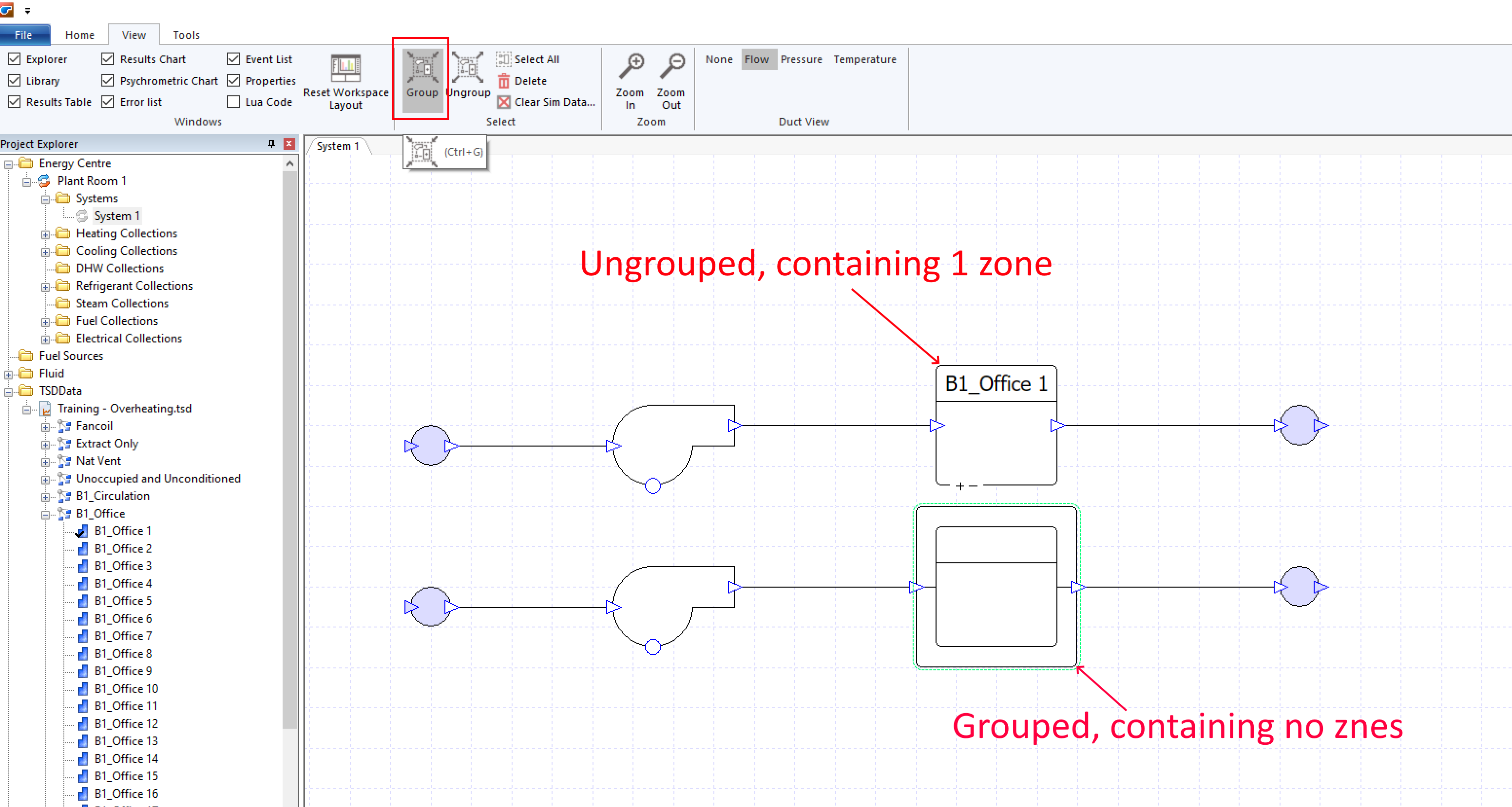
Once you have grouped a zone component, you can drag zone sets from the TSD data onto the group:
When you group multiple components that contain a zone component and assign multiple zones to the zone component, any components within the group are repeated for each of the zones in the group. For example:
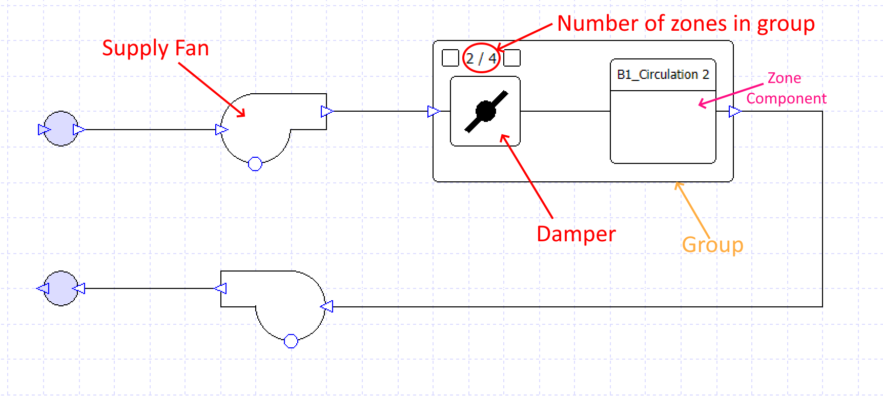
In the above schematic, there are 4 dampers – one for each zone, because the damper is in the same group as the zone component. There is only one supply fan, as it is outside of the group.
For more information about airside groups, see Airside Groups.