Plant Rooms
In Tas Systems, there is one Energy Centre which can contain multiple Plant Rooms.
Plant rooms are used to group HVAC systems together where you may which to view their aggregate results independently.
For example, if your building consists of two separate areas joined by a common area, you may which to calculate the annual CO2 emissions for these spaces independently of one another.
Additional plant rooms are also created if you use the Systems Generation Wizard to add a template system to a file which already contains a plant room.
Adding
To add a new plant room, right click on the Energy Centre and select Add Plant Room:
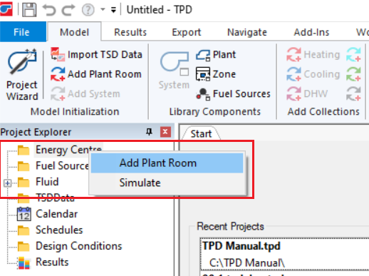
A new plant room will be created with a default system and some default collections.
Systems & Collections
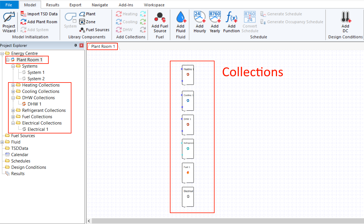
Each plant room contains:
1 Systems folder (airside systems)
Multiple Collections folders
The collections folders are:
Heating
Cooling
DHW (Domestic hot water)
Refrigerant
Fuel
Electrical
The items in the Systems folder relate to the air-side of a HVAC system. Ducts carry air from junctions through various components which can condition the air before delivering the air to a zone.
Modelling how the components condition the air is achieved in the plant schematic, as components which condition the air belong to various collections.
Some collections are joined to junctions and ducts which can carry fluids. Electrical collections are the main exception.
When you click on the plant room itself, you are presented with a view of the collections on one schematic:
If you click on a specific collection, it will be highlighted in the overall plant schematic.
The systems themselves are not shown on the plant schematic - they are shown on their own schematics when selected.
Example: Fancoil system
As an example, consider this over-simplified fancoil system, drawn on the airside system schematic:

The two fans create pressure in the system, which is used to move air across a heating coil before delivering it to the zone.
The fans belong to an electrical collection, as they get their energy from direct electricity.
The heating coil belongs to a heating collection – in this case, everything associated with that heating collection gets its heat energy from a gas-fired boiler:
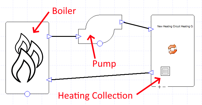
The boiler is connected to the heating collection via pipes which, in this case, carry water.
The pump provides the pressure to move the fluid around the circuit.
Of course, the boiler does not have to be gas fired - that’s where fuel sources come into play.