Zone Components
The zone components listed here can only be placed within a zone.
They are used to model in space heating and cooling and can be used to supply additional heating or cooling when the supply air cannot condition the zone appropriately.
Radiator
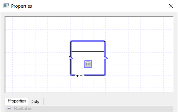
The Radiator component in TAS only provides heating to the space.
It heats the room up by convection and radiation, where the radiator’s radiant proportion is set in the internal condition of each zone.
Please note that the user will need to edit the radiant proportion of the heating emitter in the zone’s internal condition to model the radiator correctly.
You cannot use controllers with this component and it will always heat the space to the lower limit of the zone’s thermostat.
Properties
Name
This is the name of the component, it will be used in reports or error messages. You can rename components as you wish.
Description
The Description field allows the user to enter a description of the component. By default it is left blank.
Schedule
The Schedule field allows the user to apply a schedule to their component to detail the operational hours of the component.
If a schedule is applied by the user, then they should note that for all hours outside of the scheduled hours, the component will not operate. In the case of the radiator, it will not heat up the zone even if the temperature of the zone is below the lower limit of the zone’s thermostat.
The default schedule option is always on, meaning that the component will operate 24/7.
Heating Collection
Collections are a way of grouping components that share the same source of energy.
Once a component is added to a Heating, Fuel or Electrical collection, any heating load it has will be added to that collection’s demand in the plant room.
If a component is not assigned to a collection, the energy it uses will be discarded and not reported in the results. Please note you will receive a warning telling you this.
With the Heating Collection, you will be able to join: Heating, Fuel and Electrical groups. Your choice of group will depend on how the heat is being generated. For instance if the heat is being provided to the radiator from a boiler, you would choose a Heating group but if the radiator was generating the heat itself by burning fuel, you would choose a Fuel group.
Efficiency
The Efficiency field of a heating component only appears when a user chooses one of the following in the Heating Collection field:
An electrical group
A fuel group
The “None” option
This is because choosing one of these options allows the user to model a component using its energy source directly at the component to produce heat.
The Efficiency field allows the user to enter how efficient this process is, as a factor.
This field will not have any effect on the air-side results apart from the consumption results for this component now appearing in the results section of this component.
Please note while the option appears for the “none” choice in the Heating Collection field, any loads from the component will be discarded.
The user will be able to add a modifier to this field by going to the Efficiency tab which also appears when the appropriate options are chosen in the Heating Collection Field.
Duty
The duty of a component is the upper limit on the amount of power a component can provide.
If, in a certain hour, the power demand on the component is greater than the duty of the component, the component will not be able to meet this demand.
For the Radiator this would mean it wouldn’t be able to heat the air to the lower limit of the thermostat, it would fall short.
In TAS Systems, the demand (or load) met by a component is reported for each hour in the results section.
There are 3 options for setting the duty:
Unlimited – Unlimited means the component is always able to meet the demand. Please note that this option cannot be used when a controller is attached to the component.
Sized – Allows the user to size the duty on a design condition. The user will also be asked for a size fraction. Please note that to size the duty the user will need to have design conditions in their systems file.
Value – With this option the user will type in the duty of the component.
In the duty tab, you will be able to choose these 3 options as well, but with the sized and value options you will be able to add a modifier.
Fancoil Unit
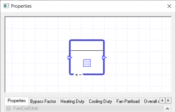
A Fancoil Unit consists of: a heating coil, a cooling coil and a fan. It can be used as the source of heating and cooling for a zone and it can also be used to provide additional heating and cooling to a zone if the supply air hasn’t been able to condition the zone appropriately.
In a set hour, the Fancoil can only heat or cool the zone; it cannot do both at the same time.
You cannot use controllers with this component and it will always heat and cool the space to the lower and upper limit of the zone’s thermostat.
It should be noted that the fancoil uses the radiant proportion from the zones internal condition in the TBD to determine the proportion of radiant energy the emitter produces. In the case of a fancoil unit, this would most likely be set to zero.
Properties
Name
This is the name of the component, it will be used in reports or error messages. You can rename components as you wish.
Description
The Description field allows the user to enter a description of the component. By default it is left blank.
Schedule
The Schedule field allows the user to apply a schedule to their component to detail the operational hours of the component.
If a schedule is applied by the user, then they should note that for all hours outside of the scheduled hours, the component will not operate.
In the case of the fancoil, neither the fan nor the coils will operate. This means that the fancoil unit will not condition the air entering it and air will only flow through the fancoil unit if it is a terminal unit and supply air is being introduced to the zone.
The default schedule option is always on, meaning that the component will operate 24/7.
Heating Collection
Collections are a way of grouping components that share the same source of energy.
Once the Fancoil unit is added to a Heating, Fuel or Electrical collection, any heating load it has will be added to that collection’s demand in the plant room.
If a component is not assigned to a collection, the energy it uses will be discarded and not reported in the results. Please note you will receive a warning telling you this.
With the Heating Collection, you will be able to join: Heating, Fuel and Electrical groups. Your choice of group will depend on how the heat is being generated. For instance if the heat is being provided to the coil from a boiler, you would choose a Heating group but if the coil was generating the heat itself by burning fuel, you would choose a Fuel group.
Cooling Collection
Collections are a way of grouping components that share the same source of energy.
Once a Fancoil unit is added to a Cooling collection, any cooling load it has will be added to that collection’s cooling demand in the plant room.
If a component is not assigned to a collection, the energy it uses will be discarded and not reported in the results. Please note you will receive a warning telling you this.
Cooling Coils can only join Cooling Groups.
Electrical Collection
Collections are a way of grouping components that share the same source of energy.
For a Fancoil unit, upon choosing an electrical collection, any electrical load due to the fan will be added to that collection’s electrical demand in the plant room.
If a component is not assigned to a collection, the energy it uses will be discarded and not reported in the results.
Fans in TAS Systems can only join Electrical groups.
Zone Position
This field allows the user to set the position and type of Fancoil Unit. There are three options to choose from:
In Zone
Terminal Unit
Parallel Fan Terminal Unit
In Zone The unit is placed in the zone and is not connected to the supply air duct.
Terminal Unit The unit is placed on the supply air duct, meaning that the supply air passes through the unit before entering the zone. The fan in this unit is placed on the air path after the supply air has been merged with the air entering the Fancoil unit from the zone.
Parallel Fan Terminal Unit Like the Terminal Unit, the unit is placed on the supply air duct but the fan is placed in the air path of air entering the Fancoil unit from the zone, before it is merged with the supply air.
The placement of the fan leads to a reduced Electrical load compared to a Terminal Unit.
Control Method
This field allows the user to set the control method of the Fancoil unit. There are three options to choose from:
CAV
VAV
On/Off
CAV With this option the Fancoil unit will have air entering it with a constant flow rate. The air is then heated and cooled to maintain the temperature in the zone.
Please note that during scheduled hours if no heating or cooling is required the fan will still operate and air will still flow through the unit at the constant flow rate.
VAV With this option the Fancoil unit will have air entering it with a variable flow rate. The air is then heated and cooled to maintain the temperature in the zone.
Please note that during scheduled hours if no heating or cooling is required the fan will still operate and air will still flow through the unit at the value set in the minimum flow rate.
On/Off With this option the Fancoil unit will only turn on when there is a need for heating and cooling during scheduled hours.
During hours where it only needs to be partially on, TAS will work out for how many minutes it will need to be on for and then takes the average air flow over the hour to display in the hourly figure in the results. When the unit is on, air will enter the Fancoil unit at a constant flow rate.
Heating and Cooling Duty
The duty of a component is the upper limit on the amount of power a component can provide.
If, in a certain hour, the power demand on the component is greater than the duty of the component, the component will not be able to meet this demand.
In TAS Systems, the demand (or load) met by a component is reported for each hour in the results section. Please note that for a Fancoil unit, the heating and cooling duties are set separately. This allows you to model a Fancoil unit which just supplies heating or cooling by setting the others duty to zero.
Currently, there are 3 options for setting the duty:
Unlimited
Sized
Value
Unlimited Unlimited means the component is always able to meet the demand.
Sized Allows the user to size the duty on a design condition. The user will also be asked for a size fraction. Please note that to size the duty the user will need to have design conditions in their systems file.
Value With this option the user will type in the duty of the component.
In the duty tab, you will be able to choose these 3 options as well, but with the sized and value options you will be able to add a modifier.
Heating Efficiency
The Heating Efficiency field of a heating component only appears when a user chooses from the following in the Heating Collection field:
An electrical group
A fuel group
The “None” option
This is because choosing one of these options allows the user to model a component using its energy source directly at the component to produce heat.
The Heating Efficiency field allows the user to enter how efficient this process is, as a factor.
This field will not have any effect on the air-side results apart from the consumption results for this component will also appear in the results section of this component.
Please note while the option appears for the “none” choice in the Heating Collection field, any loads from the component will be discarded.
The user will be able to add a modifier to this field by going to the Heating Efficiency tab which also appears when the appropriate options are chosen in the Heating Collection Field.
Bypass Factor
The Bypass Factor field determines the amount of air that will bypass the coils and thus will not be heated or cooled by the coil.
The value is entered as a factor between 0 and 1 and this factor is then multiplied against the air flow rate of the air just before the coil to determine the amount of air that will bypass the coils.
Modifiers can be added to the bypass factor using the Bypass factor tab.
Design Flow Source
The Design Flow Source option for a zone component allows the user to set the design flow rate for the component.
When the Fancoil Unit control method is set to “CAV” or “On/Off” the Design Flow Rate will be the flow rate of air through the Fancoil unit.
When the control method is set to “VAV” the design flow rate will be the maximum allowed flow rate of air through the Fancoil unit, with the minimum flow rate set by the Minimum Flow Source option.
With the Fancoil unit component, the user has the following options for the Design Flow Source field:
Value
Sized
Zone Flow Rate
Zone Fresh Air
Value
Upon choosing this option the user will be asked to enter the design flow rate.
Sized
Upon choosing this option, the user is asked to choose from the following seven sizing methods to set the design flow Rate:
Per Floor Area
Per Volume
ACH
Peak Person
Peak Person and Area
Peak Internal Condition
Delta T
Per Floor Area
Here TAS Systems asks the user to enter a value in \(l/s/m^2\) (\(cfm/\text{ft}^2\) in U.S. customary units). This value is then multiplied by the area of the zone to give the flow rate in \(l/s\) in U.S. customary units).
Please note that the user can use the size fraction field to over-size or under-size this value.
Per Volume
Here TAS Systems asks the user to enter a value in \(l/s/m^3\) (\(cfm/\text{ft}^3\) in U.S. customary units). The value is then multiplied by the volume of the zone to give the flow rate.
Please note that the user can use the size fraction field to over-size or under-size this value.
ACH
The Value field here stands for how many air changes per hour the user wishes to size the flow rate on.
Please note that the user can use the size fraction field to over-size or under-size this value.
Peak Person
TAS Systems asks the user to enter an air rate per person. TAS then uses the following formula to give the sized flow rate:
Where \(OSG\) is the occupancy sensible gain and \(OLG\) is the occupancy latent gain. Both of these values, along with the metabolic rate are read from the zones internal condition.
\(Value\) is the value entered in Systems for the air rate per person.
Please note that the user can use the size fraction field to over-size or under-size this value.
Peak Person and Area
The Peak Person and Area method allows the user to size the flow rate on both the Peak Person and Per Floor Area methods.
The user is asked to enter in their flow rates per person and per floor area. TAS then uses the value entered into the Per Person field in the Peak Person method and the value entered into the Per Area field in the Per Floor Area method. TAS will then add the results of both of these methods together and report the sum as the flow rate.
Peak Internal Condition
Please note that the Peak Internal Condition method works like the Peak Person method, but instead of asking the user for the air rate per person it uses the Outside Air rate from the zone’s Internal Condition instead.
Please note that the user can use the size fraction field to over-size or under-size this value.
Delta T
The Delta T method is the default method for sizing the flow rate for a zone.
Upon choosing this method, the user is asked to enter a heating delta T and a cooling delta T. The heating delta T value entered should be:
where the zone’s thermostat is read from the Internal Condition of the zone.
TAS Systems will then work out what is the maximum flow rate required with the supply air heated to this maximum temperature to keep the zone’s temperature above the lower limit.
Please note that this is done using the heating loads from the TSD file, as this sizing is done before the simulation.
The cooling delta T works in a similar way with the zone’s thermostat upper limit. The cooling delta T value entered should be equal to:
where the zone’s thermostat is read from the internal condition of the zone.
TAS Systems will then work out what is the maximum flow rate required with the supply air cooled to this minimum temperature to keep the zone’s temperature below the upper limit.
Please note that this is done using the cooling loads from the TSD file, as this sizing is done before the simulation.
Upon working out the flow rate needed for the heating delta T and the cooling delta T, TAS will take the max of the two as the flow rate for the zone.
Note that the values entered here do not impact the supply air temperatures. It is just used to work out the sized flow rate.
After entering the delta T values, the user will be asked to choose the design condition (or just the simulation data) to choose what days to size the flow rate on.
Please note that the user can use the size fraction field to over-size or under-size this value.
Zone Flow Rate
When this option is chosen, TAS will take the zone’s target flow rate as the flow rate through the component.
Zone Fresh Air
When this option is chosen, TAS will take the zone’s target Fresh Air rate as the flow rate through the component.
Minimum Flow Source
The Minimum Flow Source option for a zone component allows the user to set the minimum flow rate for the component.
Please note that for a Fancoil unit this option only appears when the Control Method option is set to “VAV”.
The Minimum Flow Source field gives the same four options as the Design Flow Source field but sets the minimum flow rate instead of the design flow rate. However, it should be noted that with the sized method there are an extra 3 sizing methods to choose from: Hourly Person, Hourly Person and Area, and Hourly Internal Condition.
These sizing methods work like the peak methods but are calculated for each hour.
Fan Overall Efficiency
The Fan Overall Efficiency field of the Fancoil unit allows the user to enter the overall efficiency of the fan in the Fancoil unit.
The overall efficiency of the fan is the product of its: motor efficiency, electrical efficiency, belt efficiency and aerodynamic efficiency (as there will be aerodynamic losses in the fan). Please note that this does not include any partload efficiency, which is set by the Partload field.
The user will need to enter the overall efficiency as a factor between zero and one.
Fan Heat Gain Factor
The heat gain factor of the fan is the proportion of energy used to power the fan that is converted to heat. The generated heat will warm up the air that passes through the fan.
Fan Part Load
Clicking on the Fan Partload field will take you to the Fan Partload Tab. From this tab, you will be able to edit the Partload profile of the Fancoil unit’s fan by using the graph or the table.
To see how to edit the Partload profiles, please watch the Profiles video in the TAS Systems User Guide.
Fan Pressure
The Fan Pressure field allows the user to enter the Fan Pressure. The formula for Fan Pressure is:
Chilled Beam
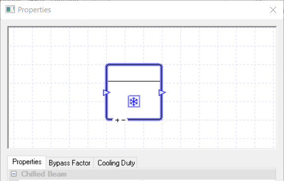
A Chilled Beam component can be used to model an active or passive chilled beam. Cold water is pumped through the beam and cools the surrounding air, which then cools down the space by convection.
Please note that the user will need to edit the radiant proportion of the cooling emitter in the zone’s internal condition to model the chilled beam correctly.
You cannot use controllers with this component and it will always cool the space to the upper limit of the zone’s thermostat.
Properties
Name
This is the name of the component, it will be used in reports or error messages. You can rename components as you wish.
Description
The Description field allows the user to enter a description of the component. By default it is left blank.
Schedule
The Schedule field allows the user to apply a schedule to their component to detail the operational hours of the component.
If a schedule is applied by the user, then they should note that for all hours outside of the scheduled hours, the component will not operate.
In the case of the chilled beam, this will mean that the beam will not cool down the zone if the zone’s temperature increases above the upper limit.
The default schedule option is always on, meaning that the component will operate 24/7.
Cooling Collection
Collections are a way of grouping components that share the same source of energy.
Once a component is added to a Cooling collection, any cooling load it has will be added to that collection’s cooling demand in the plant room.
If a component is not assigned to a collection, the energy it uses will be discarded and not reported in the results.
Please note you will receive a warning telling you this. Cooling Coils can only join Cooling Groups.
Zone Position
This field allows the user to set up the position of the chilled Beam in their zone. The two options are Active and Passive.
Active The active chilled beam is connected to the supply air ductwork. This means that some of the supply air to the zone enters through the chilled beam. This induces warm zone air into the chilled beam to be cooled.
Passive The passive chilled beam is suspended from the ceiling. It relies on natural convection for air to pass through it.
Duty
The duty of a component is the upper limit on the amount of power a component can provide.
If, in a certain hour, the power demand on the component is greater than the duty of the component, the component will not be able to meet this demand.
For the chilled beam this would mean it wouldn’t be able to cool the air to the upper limit of the zone’s thermostat, it would fall short.
In TAS Systems, the demand (or load) met by a component is reported for each hour in the results section. Currently, there are 3 options for setting the duty:
Unlimited – Unlimited means the component is always able to meet the demand.
Sized – Allows the user to size the duty on a design condition. The user will also be asked for a size fraction. Please note that to size the duty the user will need to have design conditions in their systems file.
Value – With this option the user will type in the duty of the component.
In the duty tab, you will be able to choose these 3 options as well, but with the sized and value options you will be able to add a modifier.
Bypass Factor
The Bypass Factor field determines the amount of air that will bypass the beam and thus will not be cooled by the beam.
The value is entered as a factor between 0 and 1 and this factor is then multiplied against the air flow rate of the air just before the beam to determine the amount of air that will bypass the beam.
Modifiers can be added to the bypass factor using the Bypass factor tab.
Design Flow Source
The design flow source option for a zone component allows the user to set the flow rate of the air through the component.
For a chilled beam, this will be the amount of air that passes through the beam.
With a zone component, the user has the following options for the Design Flow Source field:
Value
Sized
Zone Flow Rate
Zone Fresh Air
Value
Upon choosing this option the user will be asked to enter the design flow rate.
Sized
Upon choosing this option, the user is asked to choose from the following seven sizing methods to set the design flow Rate:
Per Floor Area
Per Volume
ACH
Peak Person
Peak Person and Area
Peak Internal Condition
Delta T
Per Floor Area
Here TAS Systems asks the user to enter a value in \(l/s/m^2\) (\(cfm/\text{ft}^2\) in U.S. customary units). This value is then multiplied by the area of the zone to give the flow rate in \(l/s\) in U.S. customary units).
Please note that the user can use the size fraction field to over-size or under-size this value.
Per Volume
Here TAS Systems asks the user to enter a value in \(l/s/m^3\) (\(cfm/\text{ft}^3\) in U.S. customary units). The value is then multiplied by the volume of the zone to give the flow rate.
Please note that the user can use the size fraction field to over-size or under-size this value.
ACH
The Value field here stands for how many air changes per hour the user wishes to size the flow rate on.
Please note that the user can use the size fraction field to over-size or under-size this value.
Peak Person
TAS Systems asks the user to enter an air rate per person. TAS then uses the following formula to give the sized flow rate:
Where \(OSG\) is the occupancy sensible gain and \(OLG\) is the occupancy latent gain. Both of these values, along with the metabolic rate are read from the zones internal condition.
\(Value\) is the value entered in Systems for the air rate per person.
Please note that the user can use the size fraction field to over-size or under-size this value.
Peak Person and Area
The Peak Person and Area method allows the user to size the flow rate on both the Peak Person and Per Floor Area methods.
The user is asked to enter in their flow rates per person and per floor area. TAS then uses the value entered into the Per Person field in the Peak Person method and the value entered into the Per Area field in the Per Floor Area method. TAS will then add the results of both of these methods together and report the sum as the flow rate.
Peak Internal Condition
Please note that the Peak Internal Condition method works like the Peak Person method, but instead of asking the user for the air rate per person it uses the Outside Air rate from the zone’s Internal Condition instead.
Please note that the user can use the size fraction field to over-size or under-size this value.
Delta T
The Delta T method is the default method for sizing the flow rate for a zone.
Upon choosing this method, the user is asked to enter a heating delta T and a cooling delta T. The heating delta T value entered should be:
where the zone’s thermostat is read from the Internal Condition of the zone.
TAS Systems will then work out what is the maximum flow rate required with the supply air heated to this maximum temperature to keep the zone’s temperature above the lower limit.
Please note that this is done using the heating loads from the TSD file, as this sizing is done before the simulation.
The cooling delta T works in a similar way with the zone’s thermostat upper limit. The cooling delta T value entered should be equal to:
where the zone’s thermostat is read from the internal condition of the zone.
TAS Systems will then work out what is the maximum flow rate required with the supply air cooled to this minimum temperature to keep the zone’s temperature below the upper limit.
Please note that this is done using the cooling loads from the TSD file, as this sizing is done before the simulation.
Upon working out the flow rate needed for the heating delta T and the cooling delta T, TAS will take the max of the two as the flow rate for the zone.
Note that the values entered here do not impact the supply air temperatures. It is just used to work out the sized flow rate.
After entering the delta T values, the user will be asked to choose the design condition (or just the simulation data) to choose what days to size the flow rate on.
Please note that the user can use the size fraction field to over-size or under-size this value.
Zone Flow Rate
When this option is chosen, TAS will take the zone’s target flow rate as the flow rate through the component.
Zone Fresh Air
When this option is chosen, TAS will take the zone’s target Fresh Air rate as the flow rate through the component.
Chilled Beam with Heating
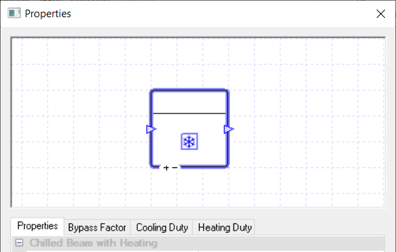
The Chilled Beam with Heating component acts similarly to the Chilled Beam component with the difference being it can also heat the air.
Just as with the chilled beam, you will need to set up the correct radiant proportion for the heating and cooling emitter in the building simulator file.
You can also use this component to model a heated beam, by setting the cooling duty of the component to zero.
As this component’s properties are very similar to the chilled beam, I will only discuss the additional options.
Please note that the Bypass Factor field will only affect the results when the beam is cooling and the Cooling Duty field for the chilled beam with heating is the same as the Duty field for the chilled beam.
Properties
Heating Collection
Collections are a way of grouping components that share the same source of energy.
Once the chilled beam with heating is added to a Heating, Fuel or Electrical collection, any heating load it has will be added to that collection’s demand in the plant room.
If a component is not assigned to a collection, the energy it uses will be discarded and not reported in the results. Please note you will receive a warning telling you this.
For the chilled beam with heating, the heating collection only deals with the energy used by the beam for heating. With the Heating Collection field, you will be able to join: Heating, Fuel and Electrical groups.
For instance if the heat is being provided to the beam from a boiler, you would choose a heating group but if the beam was generating the heat itself by burning fuel, you would choose a fuel group.
Heating Duty
The duty of a component is the upper limit on the amount of power a component can provide.
If, in a certain hour, the power demand on the component is greater than the duty of the component, the component will not be able to meet this demand.
For the chilled beam with heating, setting the heating duty too low would mean it wouldn’t be able to heat the air to the upper limit of the zone’s thermostat, it would fall short.
In TAS Systems, the demand (or load) met by a component is reported for each hour in the results section.
Currently, there are 3 options for setting the duty:
Unlimited – Unlimited means the component is always able to meet the demand.
Sized – Allows the user to size the duty on a design condition. The user will also be asked for a size fraction. Please note that to size the duty the user will need to have design conditions in their systems file.
Value – With this option the user will type in the duty of the component.
In the duty tab, you will be able to choose these 3 options as well, but with the sized and value options you will be able to add a modifier.
Heating Efficiency
The Heating Efficiency field of a heating component only appears when a user chooses from the following in the Heating Collection field:
An electrical group
A fuel group
The “None” option
This is because choosing one of these options allows the user to model a component using its energy source directly at the component to produce heat.
The Heating Efficiency field allows the user to enter how efficient this process is, as a factor.
This field will not have any effect on the air-side results apart from the consumption results for this component will also appear in the results section of this component.
Please note while the option appears for the “none” choice in the Heating Collection field, any loads from the component will be discarded.
The user will be able to add a modifier to this field by going to the Heating Efficiency tab which also appears when the appropriate options are chosen in the Heating Collection Field.
DX Coil Unit
A DX Coil unit is a Fancoil unit but instead of having a heating coil and a cooling coil, it has a DX coil which provides both heating and cooling.
You cannot use controllers with this component and it will always heat and cool the space to the lower and upper limit of the zone’s thermostat.
Properties
As the DX Coil unit properties are mostly the same as the Fancoil unit I will only discuss the one property that isn’t in the Fancoil unit’s properties, the Refrigerant Collection property. This replaces the Heating and Cooling Collection fields in the Fancoil unit’s Properties.
Refrigerant Collection
Collections are a way of grouping components that share the same source of energy.
Once a component is added to a Refrigerant collection, any heating or cooling load it has will be added to that collection’s refrigerant demand in the plant room.
If a component is not assigned to a collection, the energy it uses will be discarded and not reported in the results.
As the DX Coil uses refrigerants, you can only join refrigerant Groups.