Introduction
When you are proficient with Tas Systems, you are quite likely to use the Systems Generation wizard to quickly generate the systems present in your building and then modify them as needed.
It is quite rare that you will need to create a system entirely from scratch, but it does provide an excellent way to learn how to use the software effectively.
In this section, we will create some basic systems from scratch in order to learn how to use Tas Systems, explaining the concepts as we go.
Note
Remember! Our systems generation wizard takes the hard work out of creating systems, so don’t forget to use it!
A you read through this manual, it’s a good idea to follow along.
If there are any terms you don’t understand, check the glossary and if you would like any more information about a specific component or its input, check the components section of this manual.
What is Tas Systems
Tas Systems is a component based plant modelling application which can be used to design, simulate and improve new and existing Heating, Ventilation and Cooling (HVAC) systems.
It is used in conjunction with a building simulator results file to model how the heating and cooling demands for a zone could be met.
Component based
Component based modelling is one of the main strengths of Tas Systems; it means that systems are created by linking various components together such as fans, pumps, boilers and heating/cooling coils.
This leads to an incredible amount of flexibility as it means non-standard custom systems can be easily created with no more difficulty than standard systems, and it is essential for innovative design.
Non-component based systems modelling applications are very rigid and cannot be easily altered as there is usually a fixed set of components in each template system which cannot be fully modified and controlled.
In Tas Systems, you can also group together components and save these as templates for future use.
There is also an extensive library of pre-made common systems that can be easily edited and modified as if you’d created it from scratch.
Our templates and component libraries means Tas Systems has both the benefits of component based and non-component based modellers.
What is it used for
Tas Systems can be used for anything that requires detailed analysis of a HVAC system as results can be displayed for individual components as well as the systems as a whole.
Common uses include:
Sizing HVAC systems
Calculating energy demand figures
Calculating energy/CO2 consumption figures
Calculating unmet hours for a given system
Calculating energy costs
Calculating internal temperatures for complex systems
Results are calculated for every component for every hour of the year so yearly, daily, monthly and hourly values for temperatures, flow rates, demand and consumption can easily be obtained.
How does systems work?
After you have created geometry in the 3D modeller, exported to the building simulator, specified the internal gains and heating/cooling setpoints and simulated the building, you will have a building simulator results file with the following results:
Hourly internal temperatures throughout the year
Hourly zone loads for heating and cooling
Thermal response factors for each zone
If, for example, you specified that a space in your building should be heated to 21°C you may find that 1000W of sensible heat energy is required to maintain that temperature for a given hour in the year. This does not mean that 1000W of energy will be consumed, as there are many ways to heat a space including:
Direct electricity (electric radiators, for example)
Heat pumps (e.g. dx coils, which are more than 100% efficient)
Heat recovery units (which re-capture waste heat)
If heat pumps are present and heat recovery units are present, the actual energy consumption may be less than the sensible load.
This is where Tas Systems comes into play; taking the building simulator results file as an input, Tas Systems allows you to model the ways in which you could meet the energy demands for the building.
The thermal response factors in the results file measure how the zones respond to an addition or removal of energy, so we can use the results file to re-calculate internal temperatures when modelling specific systems.
Before you begin
Throughout this section, we will be using our Training Course model as it has a mix of HVAC systems, natural ventilation and unconditioned spaces.
If you would like a copy of this model, you can download it from our e-training website or contact us for a copy.
You can also use your own models.
Note
Your building simulator file should be setup such that the internal temperatures and ventilation rates are as close to the Tas Systems values as possible.
For example, if your space is naturally ventilated in the building simulator file, it should be naturally ventilated in Tas Systems.
If your space is heated to 21°C and cooled to 24°C in the building simulator, it should be in Tas Systems too.
If your space has 3ACH of fresh air, it should have 3ACH of fresh air in Tas Systems even if there is heat recovery.
Warning
If your Building Simulator results are wildly different to the Tas Systems results, the simulation may fail to converge and the results may be inaccurate.
At this point, it is a good idea to jump to the User Interface section to get a rough feel for the user interface before getting started.
Importing TSD Data
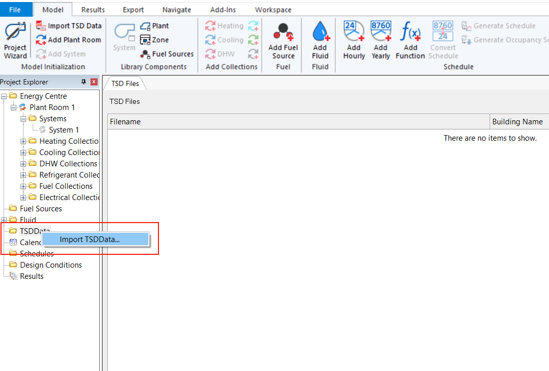
Once you have created a new Tas Systems file, one of the first things you’ll probably want to do is import a TSD file.
Right click on the TSD Data folder in the tree on the left, and select Import TSD Data:
You’re now ready to drag the imported zones data onto zone components.
When you import TSD data, Tas Systems extracts information about which zones are in your building and details about these zones such as:
Floor area
Volume
The surfaces in the zone
Tas Systems also extracts information about any design days that may be in the Building Simulator (TBD) file associated TSD file.
This information is available when you are creating your airside systems and various collections– for example, you may wish to use a particular zone surface as a PV panel. As another example, you may wish to specify air flow rates in terms of the floor area.
When you simulate a Tas Systems file, additional information is read from the TSD file such as the internal temperatures. Information from the associated TBD file is also extracted – for example, the information in the System Parameters section of the internal condition applied to a zone for a specific hour:
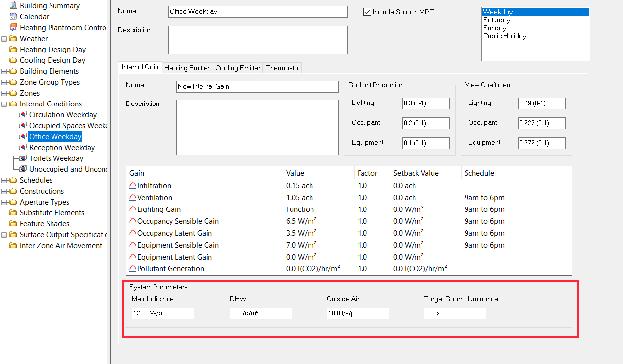
System parameters in an internal condition in the Building Simulator.
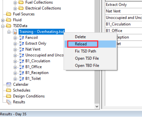
If you change anything in your Building Simulator file that will affect the results of the dynamic simulation, you should re-simulate your Building Simulator file and update your TSD file in Tas Systems:
Typical Workflow
The most common way to use Tas Systems is to use the Systems Generation wizard, as it guides you through the following steps.
Import TSD Data
Add a plant room
Create the Airside systems
Create the supporting collections (heating, cooling etc)
Assign fuel sources
Simulate & check results
When you’re creating the Airside Systems and the collections, if you know the capacity and efficiencies of the equipment you can enter them here or you can specify how the equipment should be sized.
Checking the results is very important, as Tas Systems will help you identify problems with the design.