Tas Systems Project Wizard
This section explains the steps of the Tas Systems Project Wizard (TPDx)
TPDx generates the water-side and air-side schematics from the parameters entered into the wizard. This data is saved as a TPDx file and can be used in other projects.
TPDx is opened by clicking on “Project Wizard” in the “Model” tab of the Ribbon Control.
Project Type
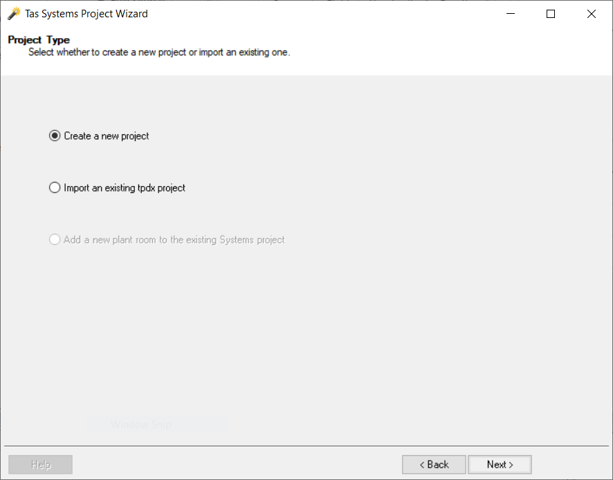
The options available are:
Create a new project: The most commonly-used option. Starts a fresh TPDx project.
Import an existing tpdx: To re-use a previously-created TPDx file.
Add a new plant room to the existing Systems project: Not available in an empty TPD file. Can be used to run the TPDx wizard a second time for a TPD file which is only partially complete.
Project Setup
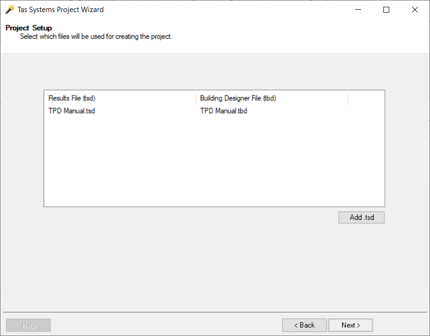
The TPD simulation will be based on the zone results from a TSD file. It is possible to combine the results of multiple TSD files in one TPD.
Zone Assignment
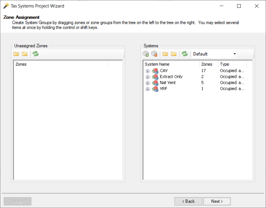
On the left-hand side appears a list of all the zones in the imported TSD(s). On the right-hand side the user can create and name air-side systems.
When a zone is dragged from the left side to the right side, it no longer appears on the left side so you know which zones have not been applied to a circuit. It also ensures that a zone cannot be applied to more than one circuit.
A zone does not have to be applied to a system and some zones should not be applied to any circuits. These would include zones for PV panels, SHW, unconditioned roof surfaces or external zones.
If a zone group is dragged from the left side to the right side, and not applied to an existing system, a new system is automatically generated.
Zones can be moved between systems.
Air-side Configuration
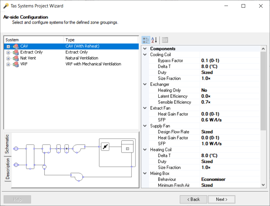
For each of our groups we can now apply an air side system. We can also edit certain component properties - these properties are explained elsewhere in this guide. These properties, and others, can also be edited later after the wizard has been used to generate the systems.
The “Description” tab explains how the system will operate; this assists the user to choose the system which most closely matches their real-life system. The “Schematic” tab shows a preview of how the system will look.
Heating Circuit Configuration
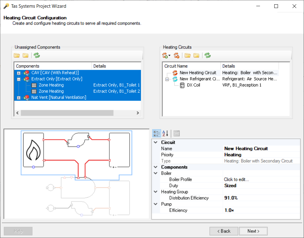
On the left-hand side appears a list of all the heating components in the created systems.
On the right-hand side the user can create heating circuits; boiler-based circuits for hot water systems, heat pumps for refrigerant systems.
We can also edit certain component properties - these properties are explained elsewhere in this guide. These properties, and others, can also be edited later after the wizard has been used to generate the systems.
When a component is dragged from the left side to the right side, it no longer appears on the left side so you know which components have not been applied to a circuit. It also ensures that a component cannot be applied to more than one circuit.
Boiler Editor
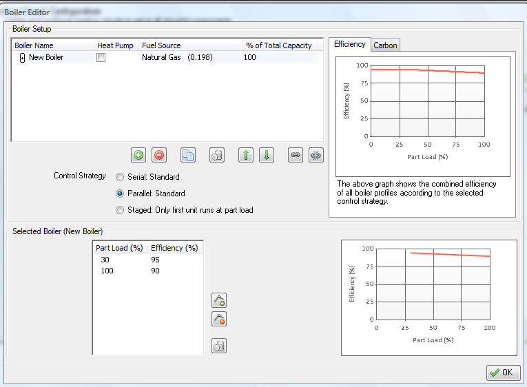
For each boiler, the part load performance map data can be added.
Each boiler has a fuel source. This determines the CO2 emissions factor and the tariff used by the boiler. Both the CO2 emissions factor and tariff are editable.
The capacity of the boiler is the percentage of the total heating capacity that boiler will meet. If you have multiple boilers, this column must add up to 100%.
The boilers can run in parallel, serial or staged.
If the boilers are set up to run in parallel, a boiler’s capacity determines the proportion of a given hour’s heating demand met by that boiler. In this case the order that the boilers appear in the list has no effect on the results.
If the boilers are set up to run in serial, the hourly demand as a proportion of the total capacity is calculated. If this value is lower than the capacity of the first boiler, then only the first boiler turns on. If the value is greater than the first boiler’s capacity then the first boiler runs at full load and other boilers do the remainder. The order the boilers appear in the list is the order they switch on.
If the boilers are set up to have staged operation, then the boilers other than the first boiler run at full load when required and the remaining load is picked up by the first boiler.
When modelling a heat pump, do not enter a COP value for heating. Instead multiply the COP by 100 and enter that value into the efficiency fields.
TEXT
Cooling Circuit Configuration
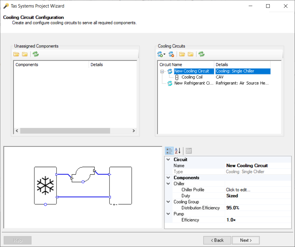
On the left-hand side appears a list of all the cooling components in the created systems.
On the right-hand side the user can create cooling circuits.
We can also edit certain component properties - these properties are explained elsewhere in this guide. These properties, and others, can also be edited later after the wizard has been used to generate the systems.
When a component is dragged from the left side to the right side, it no longer appears on the left side so you know which zones have not been applied to a circuit. It also ensures that a component cannot be applied to more than one circuit.
Chiller Editor
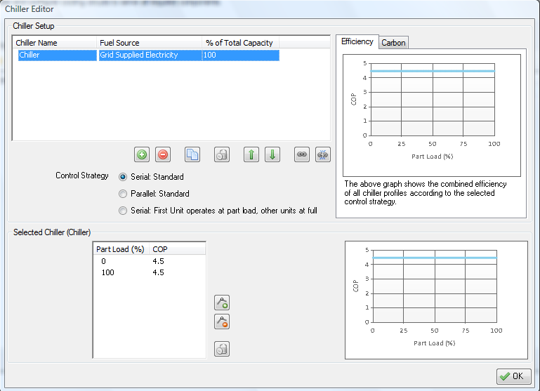
For each chiller, the part load performance map data can be added.
Each chiller has a fuel source. This determines the CO2 emissions factor and the tariff used by the chiller. Both the CO2 emissions factor and tariff are editable.
The capacity of the chiller is the percentage of the total cooling capacity that chiller will meet. If you have multiple chillers, this column must add up to 100%.
The chiller can run in parallel, serial or staged.
If the chillers are set up to run in parallel, a chiller’s capacity determines the proportion of a given hour’s cooling demand met by that chiller. In this case the order that the chillers appear in the list has no effect on the results.
If the chillers are set up to run in serial, the hourly demand as a proportion of the total capacity is calculated. If this value is lower than the capacity of the first chiller, then only the first chiller turns on. If the value is greater than the first chiller’s capacity then the first chiller runs at full load and other chillers do the remainder. The order the chillers appear in the list is the order they switch on.
If the chillers are set up to have staged operation, then the chiller other than the first chiller run at full load when required and the remaining load is picked up by the first chiller.
When modelling a heat pump, do not enter a COP value for cooling. Instead multiply the COP by 100 and enter that value into the efficiency fields.
DHW Circuit Configuration
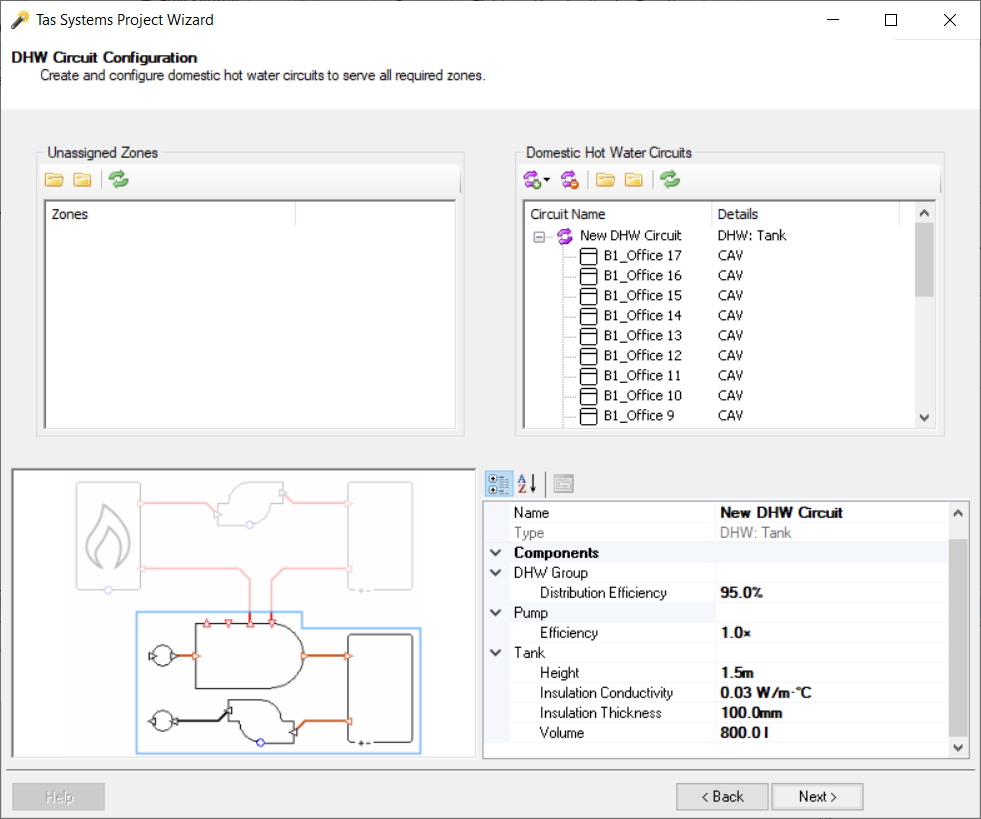
On the left-hand side appears a list of all the zones in the created systems.
On the right-hand side the user can create Domestic Hot Water circuits.
We can also edit certain component properties - these properties are explained elsewhere in this guide. These properties, and others, can also be edited later after the wizard has been used to generate the systems.
When a zone is dragged from the left side to the right side, it no longer appears on the left side so you know which zones have not been applied to a circuit. It also ensures that a component cannot be applied to more than one circuit.
Renewables Configuration
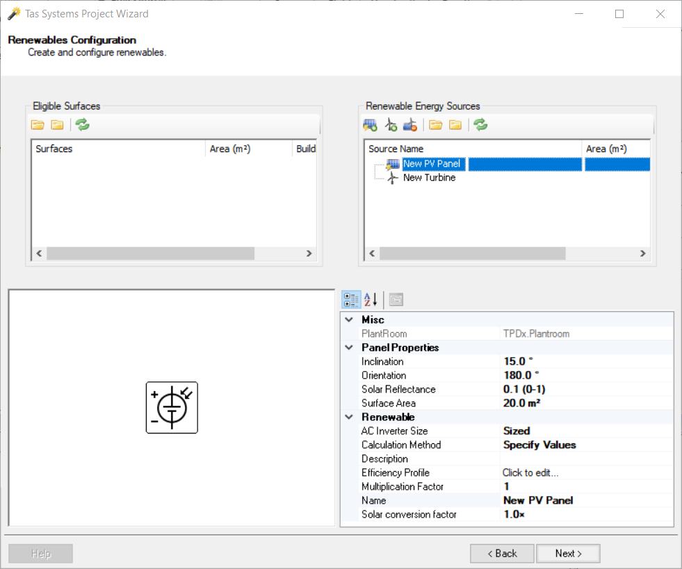
Wind turbines, PV panels and SHW panels can be modelled.
Only PV panels and wind turbines can be added on this page. To add a SHW panel, you will need to select the appropriate heating circuit on the heating circuit configuration page.
You can model SHW and PV panels either by creating the panel in the 3D modeller, or by specifying the panel’s parameters here. Surfaces with relevant output specifications, if any, will appear on the left-hand side of this page.
Which method you will use will depend on the Calculation Method field. If it is set to “Use Zone Surface”, then you would need to apply an eligible surface to the panel.
If the Calculation Method field is set to “Specify Values”, then you can enter the inclination, orientation, solar reflectance and surface area of the panel. The software will then calculate the amount of solar energy that would be absorbed by an un-shaded panel. Any reflected solar energy from the ground will not be accounted for by this method.
When entering the panel’s inclination angle, an angle of 0º would mean the panel is positioned horizontally while an angle of 90º would mean the panel is positioned vertically. The panel’s orientation angle is the angle clockwise from north. Due north would be 0º, due east would be 90º, and so on.
Fuel Source Configuration
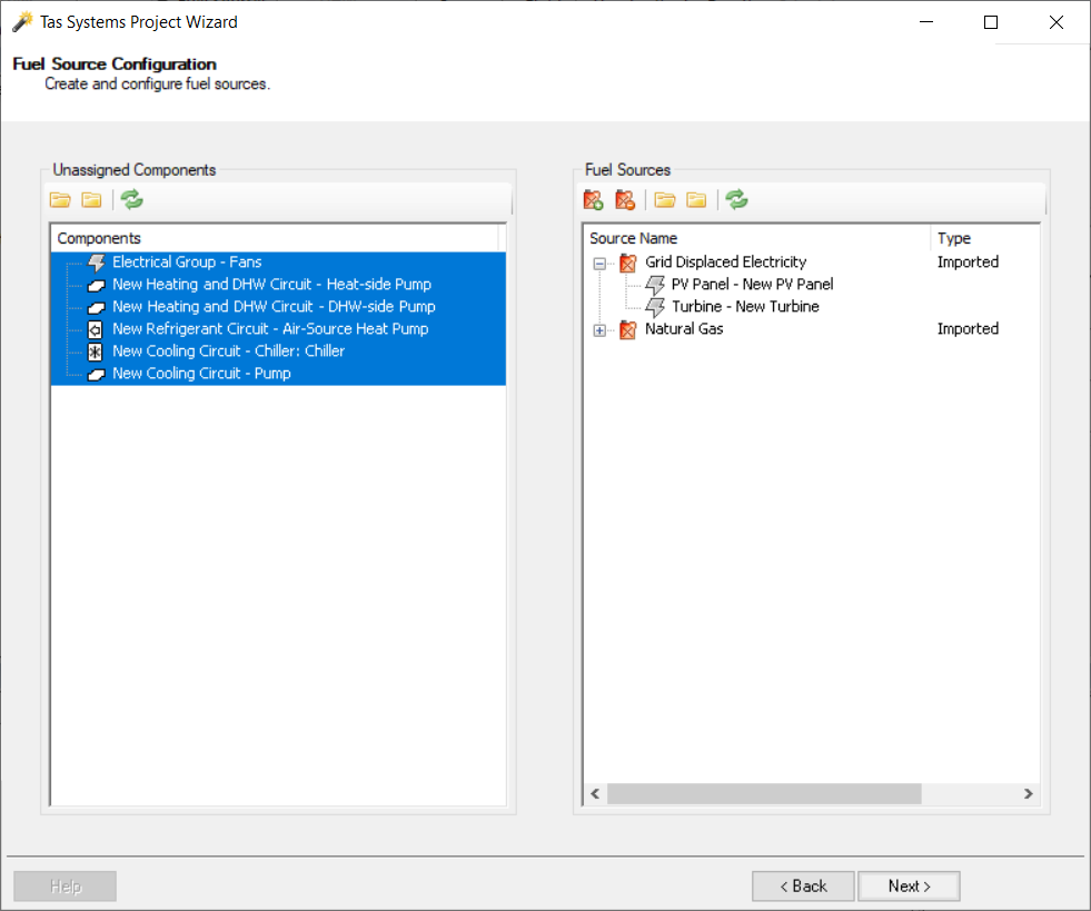
Fuel sources are used to determine the CO2 factors and tariffs used by individual components in the project.
Unassigned components have a CO2 factor and tariff rate of zero.
The default CO2 factors are taken from the 2010 UK Building Regulations. These values cannot be edited using the wizard, but can be edited once within Systems.
Unassigned components are listed on the left-hand side. On the right-hand side the user can add fuel types.
Design Condition Configuration
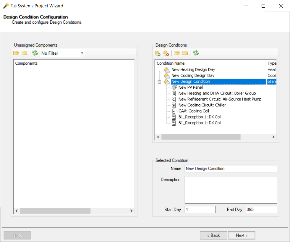
If components other than fans have been set to size, then design conditions need to be set up.
If the imported TBD file had design days, they would appear in the Design Conditions list.
Dynamic design conditions can be created and components can be assigned to them.
Fans are sized on the peak of all the design conditions and the simulation run.
File Creation
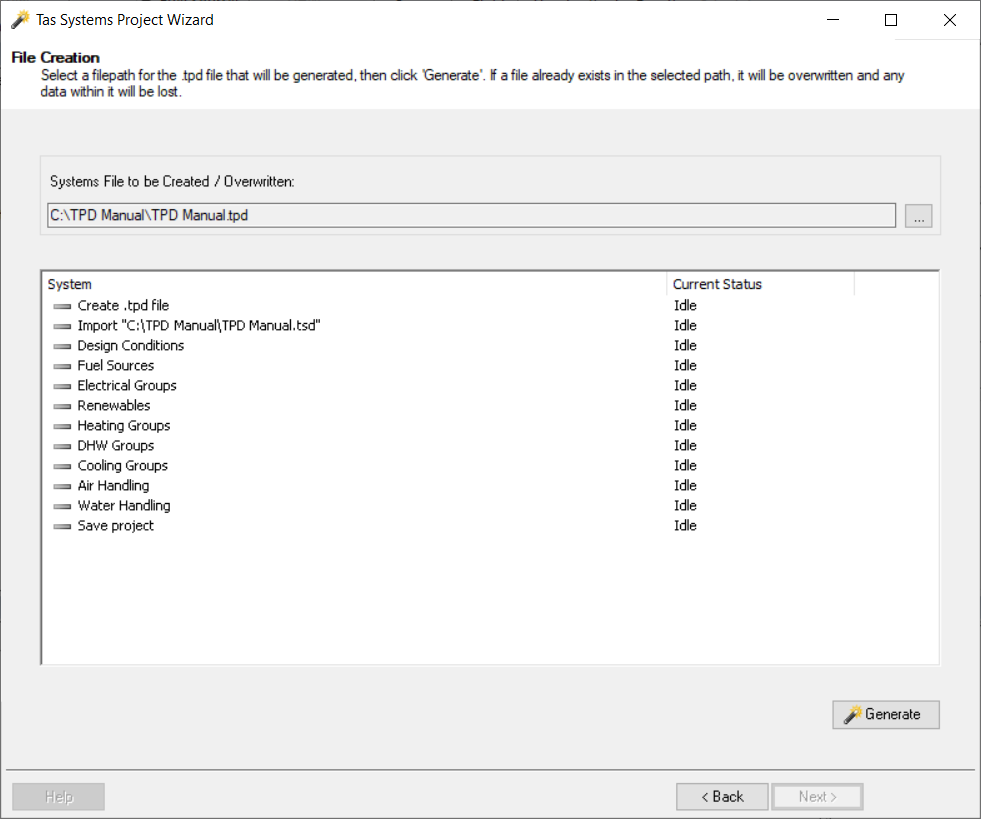
The Generate option creates the air side and water side schematics in the Tas Plant Data file.
The inputs in the wizard are saved as a TPDx file.
Re-using TPDx files with a different TSD
A previously-created TPDx file can be re-used with a different TSD, provided that it is based on the same TBD (some zones must match). This can be very useful if you have multiple copies of the same TBD (e.g., testing construction or internal condition changes) but want to apply similar HVAC. It can also be useful if you have done a UK regulations project using the studio and now want to carry out a more detailed energy model.
On the Project Type page of the wizard, select “import an existing tpdx project”.
You will be asked whether you want to keep using the TSD which was originally related to the TPDx file, or select a different TSD file.
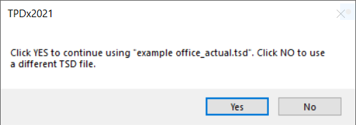
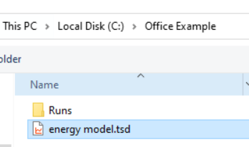
If you select “No”, you can then select a TSD file to replace the original.
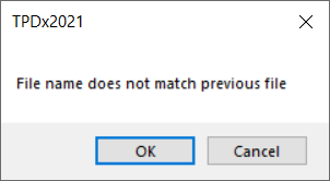
If the TSD file name differs from the original, you will see a message box; if the name change is intentional, press “OK” and carry on.