Building Summary
The building summary is the first page that is seen when a tbd is produced or opened, and it displays some information taken from the 3D model, and some global parameters which can be edited. Building Name and description are brought in from the 3D model but can be edited here and any edits will be used in the next part of the software, the Results Viewer.
The number of Zones, Building Elements & Apertures are read from the 3D model and represent the number of unique instances of each. Apertures include any element that has had an Aperture Type assigned to it, or any null wall. Total Zone Floor Area is the area of zoned spaces in the model.
Note
If a space is not zoned its floor area will not be counted here.
Natural Ventilation Calculations
The following settings will affect the Natural Ventilation Calculations:
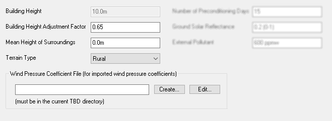
The Building Height represents the highest point of any space in the 3D model. If the highest drawn point is not actually your building but a surrounding building only drawn in for shading purposes, then you must tell Tas the highest point of your model by setting the Building Height Adjustment Factor. For example, if your building has a ridge height of 6.5m, but a surrounding building has a height of 10m, the Building Height would read 10m on this page. You would need to set the Adjustment Factor to 6.5/10 = 0.65.
The Mean Height of Surroundings tells the software that there is surrounding terrain, or building features that will stop any wind up to a certain height. This might be a fence around the building, or a raised bank or similar. Note this will be ignored if a Wind Pressure Coefficient File is used.
The Terrain Type is used to calculate the wind speed and pressure around the site, by adjusting the values in the weather file. The different terrain types are described in BS59255:1991, and relate to the Tas definitions in the following way:
Terrain Type (BS5925:1991) |
Tas Terrain Type |
|---|---|
Open flat country |
Open |
Country with scattered windbreaks |
Rural |
Urban |
Town |
City |
City |
If the user has specific information about wind pressures around the local site then these can optionally be incorporated into the model by adding a Wind Pressure Coefficient File. This should be a text (.txt) file with the following format:
Tip
How to Set Up a Wind Pressure Coefficient File
Information must be entered in lines as follows, with values on the same line being separated by spaces.
1st line:
No. of wind directions The number of wind directions for which pressure coefficients are specified (in the range 1 to 32)
Each subsequent line:
Wind Directions Each of the wind directions, specified clockwise in degrees from North (0-359°)
Zone Number, Surface Number: The number of the zone and surface for which wind pressure coefficients are specified. There must be a line in the file for each aperture in the building, including internal apertures (for which the wind pressure coefficients are ignored).
Wind pressure coefficients: The wind pressure coefficients for the specified aperture, for each wind direction specified on the first line.
The wind pressure coefficients are defined in such a way that the wind pressure on an aperture is:
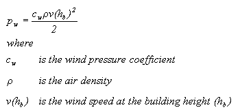
These wind pressure coefficients will override Tas’ algorithms for estimating wind pressures on the building facade. See the Tas theory manual for further information.
Preconditioning
The simulation will (generally) start on day 1 of the year but of course in reality the building is occupied for many days before this, meaning that internal heat gains have built up, heating has been on, etc, and energy is stored within the thermal mass of the building fabric. To allow for this, tbd simulates a number of days before day 1 of the simulation, these days are called Preconditioning Days. The user can set how many days to run preconditioning and we recommend 15 days, although this can be reduced if necessary to increase simulation time, particularly in a lightweight structure as preconditioning should have less effect.
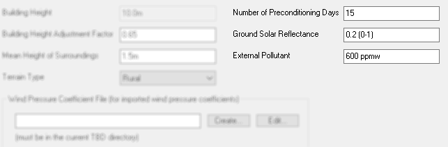
Ground Solar Reflectance may need to be adjusted if the building you are modelling is surrounded by unusual terrain, such as snow or water, which would have a higher solar reflectance.
In building pollutant levels can be modelled in Tas, and generally the user will be modelling CO2. The External Pollutant level specifies the density of pollutants (CO2) in the outside air which influences the effectiveness of ventilation at reducing internal pollutant (CO2) levels. It should be set appropriately if the user is interested in assessing internal CO2, as should CO2 generation rates in the internal conditions.
On the left hand sie of the screen is a ‘tree-view’ giving access to each of the parts of the tbd.