Constructions
Constructions are used in the Building Simulator to model conduction heat transfer and storage due to the fabric of the building.
Each construction is composed of material layers; the building simulation models the interaction of heat flow through each of these layers individually.
There are two types of construction in the Building Simulator:
Opaque Constructions
Transparent Constructions
Opaque constructions are used to model building elements that do not involve the transfer of solar energy such as walls and floors. Transparent constructions are used to model transparent and translucent glazing, which allow solar energy to enter a space.
Each surface in the Building Simulator has a Building Element. Constructions are assigned to building elements.
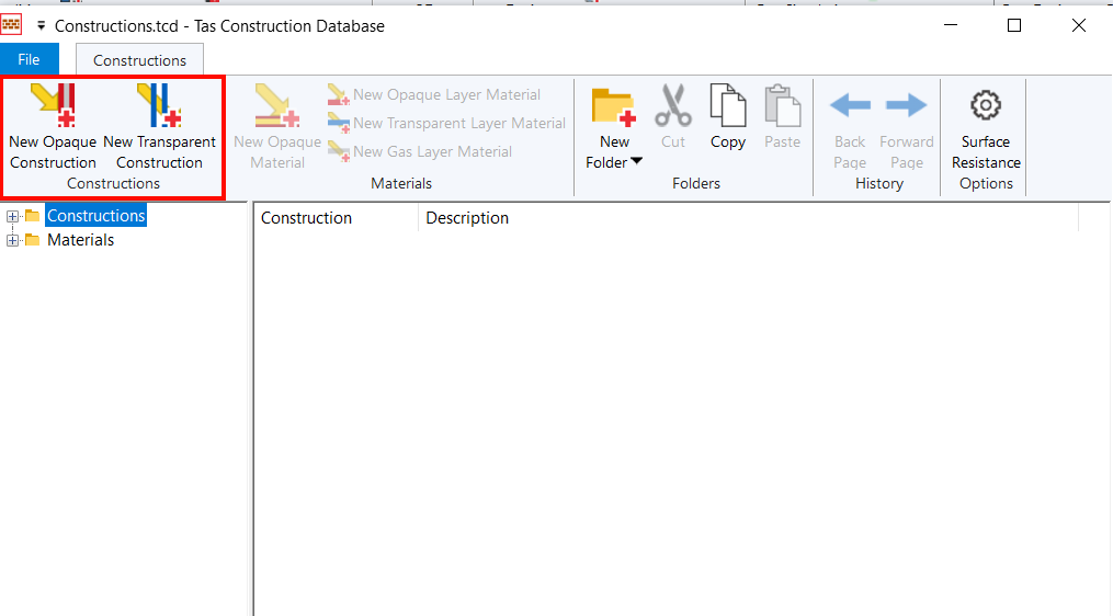
Adding Constructions
New constructions can be created in the Tas Constructions Database:
Once you have added material layers to the construction, you can drag and drop the construction from the database into the Building Simulator file:
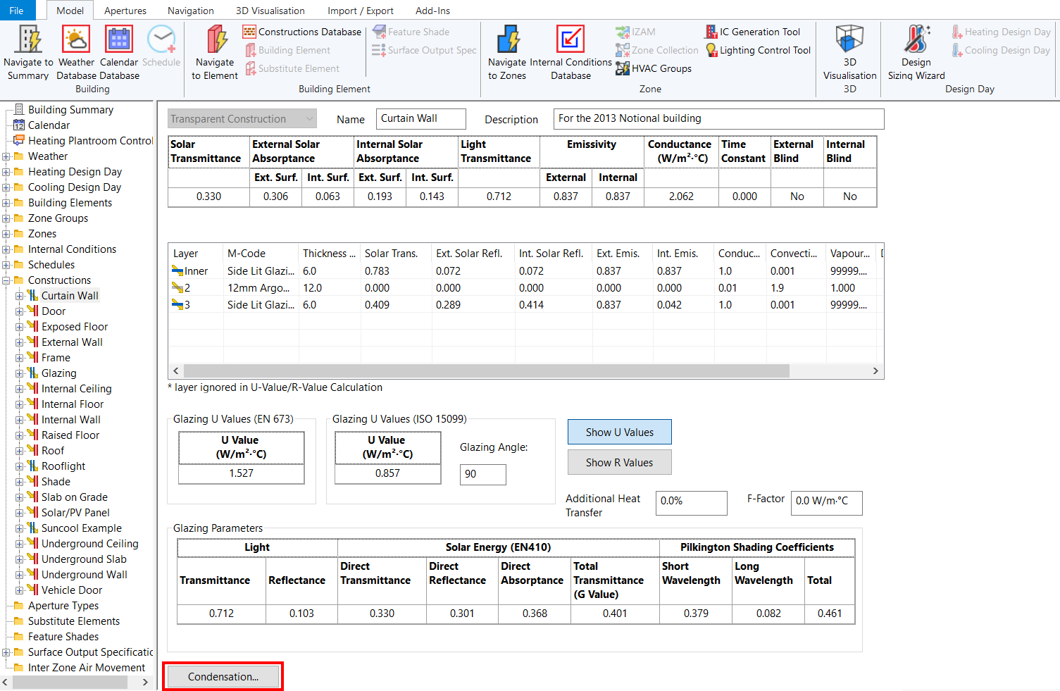
Condensation
You can examine the rate of interstitial condensation on each building component in Tas, by pressing the Condensation button on a construction:
Tas calculates the condensation rate through the construction based on BS EN ISO 13788. To assess the risk of condensation to a structure, this standard has the following criteria:
To avoid mould growth the thermal design of the structure should be sufficient to keep relative humidity at internal surfaces below 80% in the most severe month of the year, given internal conditions appropriate to the use of the building.
Any interstitial condensation that occurs within the structure in the winter should all evaporate during the next summer to prevent an accumulation from year to year.
If interstitial condensation occurs over the winter and evaporates in the summer, the risk of degradation to the materials present should be considered in terms of the maximum accumulated condensation.
Though there is no fixed number as to the amount of condensation that would cause problems, the following guidelines can be useful in most situations:
Extensive work on flat roofs with continuously supported membranes has shown that they will perform satisfactorily if the winter peak in condensate retained within the roof does not exceed 350 g/m2 provided that there is no accumulation from one year to the next.
The prediction of any amount of condensate on wood or wood based materials, especially structural components, should be treated with great caution and steps should be taken to eliminate it.
An exterior leaf of masonry, which will be wetted by the rain can withstand substantial amounts of interstitial condensate without adverse consequences.
Condensate on impermeable surfaces such as a metal roof or plastic will not always cause any damage where it occurs but can run or drip onto more vulnerable areas. The effect of various amounts of condensate is summarized in the following table.
Amount of Condensate (\(g/m^2\)) |
Effect |
0 - 30 |
A fine mist that does not run even on vertical surfaces. |
30 - 50 |
Droplets forming that will start to run on vertical surfaces. |
50 - 250 |
Large drops forming that will run on sloping surfaces. \(70g/m^2\) will run at a 45° slope. \(150g/m^2\) will run at a 23° slope. |
>250 |
Drops forming that are large enough to drip from horizontal surfaces. |
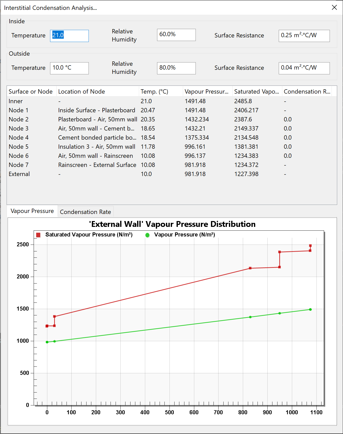
The interstitial condensation analysis window is as follows:
Inputs
Inside Temperature
The dry bulb temperature in the zone, in °C.
Inside Relative Humidity
The relative humidity inside the zone. This value is entered as a percentage.
Internal Surface Resistance
This is the surface resistance for the surface within the zone. It is measured in \(m^2K/W\). This value is usually 0.13 for glazing and frames and 0.25 for all other internal surfaces.
Outside Temperature
The external dry bulb temperature, in °C.
Outside Relative Humidity
The external relative humidity. This value is entered as a percentage.
Internal Surface Resistance
This is the surface resistance for the surface exposed to the outside. It is measured in \(m^2/KW\). This value is usually 0.04 for all external surfaces.
Condensation Rate Table
Surface or Node
The name and number of the node. The nodes are placed on the surfaces and where two layers of the constructions meet. There are also rows for inside and outside conditions.
Position of Node
This shows where the node is. It gives the material name of the two layers the node is touching or the name of the surface it is on.
Temperature
In the case of the ‘Internal’ and ‘External’ rows this is the dry bulb temperature. For the others it is the temperature at the node. Measured in °C.
Vapour Pressure
The vapour pressure at the node or surface. This is measured in \(N/m^2\).
Saturated Vapour Pressure
The saturated vapour pressure at the node or surface. This is measured in \(N/m^2\).
Condensation Rate
The condensation rate at the node or surface. It is measure in \(kg/m^2/s\). If this value is positive then condensation has occurred and the row will become highlighted.
Graphs
Vapour Pressure
This displays the vapour pressure and saturated vapour pressure in \(N/m^2\) for each node. The x-axis goes from ‘External’ through all the nodes, finishing with ‘Internal’.
When the vapour pressure line exceeds the saturated vapour pressure, there is a risk of condensation - the rate of which is visualised in the condensation rate graph.
Condensation Rate
This displays the condensation rate in \(kg/m^2/s\) for each node or surface.
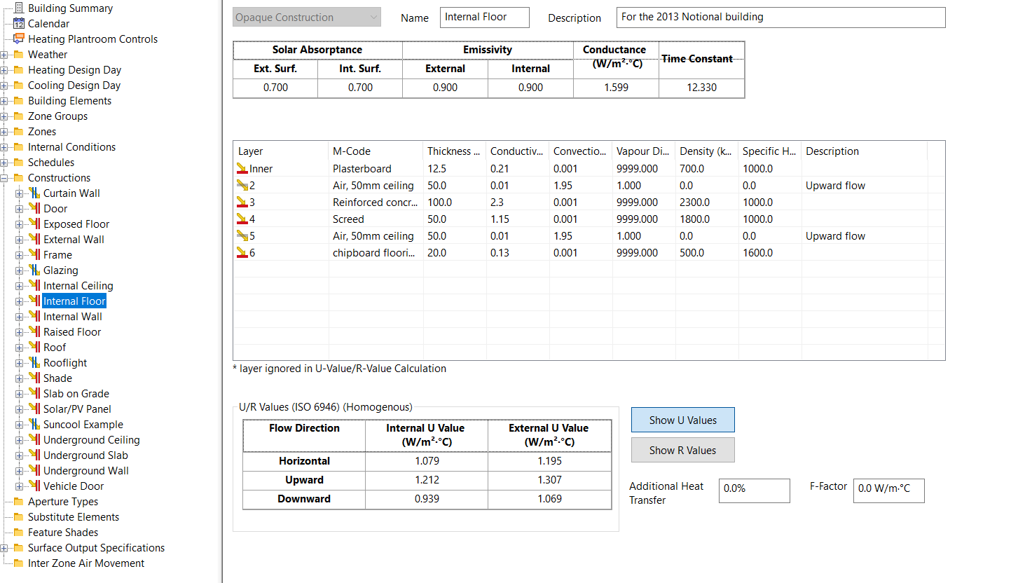
Opaque Constructions
Clicking on an opaque construction allows you to see a summary of the thermal properties of the construction, the material layers, and options for adjusting the heat transfer.
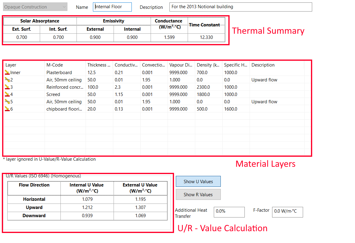
Materials Table
The materials table shows a summary of the material layers composing the construction, with the first layer being the innermost layer.
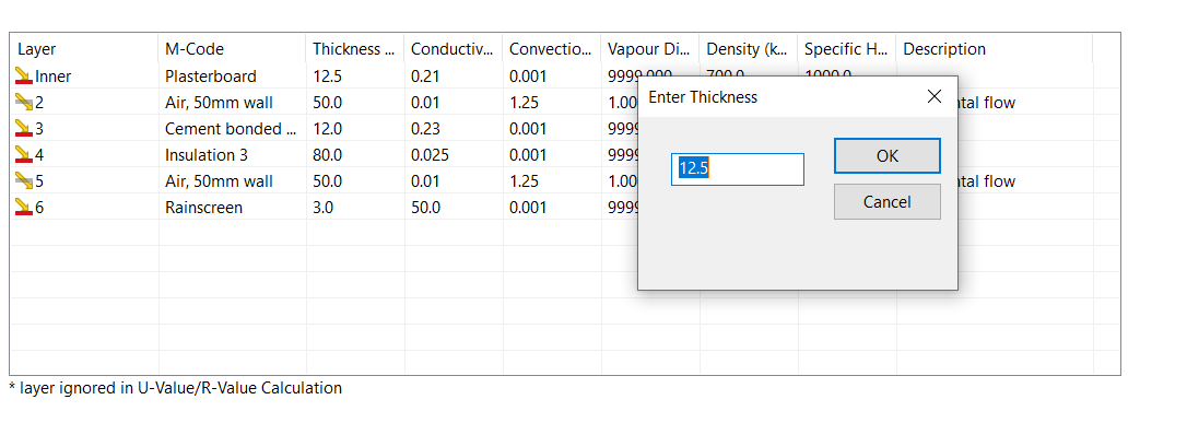
The thickness of the construction displayed in this table is used in the simulation, and can differ from the thickness set in the material layer properties. To edit, double click on the material:
Solar Absorptance
The solar absorptance describes the fraction of incident solar radiation that is absorbed by the construction. This is displayed for both the external and internal surface.
Emissivity
The emissivity is the amount of long wave radiation absorbed by the material, and is displayed for both the internal and external surfaces of the construction.
Conductance
The conductance is the amount of heat flux per unit temperature difference across the construction in the steady state.
The conductance applies to the construction alone and does not include the effects of surface heat transfer.
Time Constant
The time constant is the approximate time taken for the construction to regain thermal equilibrium following a sudden change in either of its surface temperatures. This gives a measure of the thermal mass/inertia of the construction.
Lightweight constructions such as plasterboard partitions have a time constant less than 1 hour, but a construction composed of 1m of concrete has a time constant of about 50 hours.
U-Values
The U-Values for the construction, based on the material layers composing the construction and ISO 6946, are calculated for each direction of heat transfer both internally and externally.
Note
The Building Simulator does not use the u-values as part of the simulation, and instead models the thermal properties of each material layer in detail including the effect of thermal mass. This is more accurate.
U-values represent the amount of heat transfer per degree of temperature difference across the construction, per unit area.
R-Values
The R-value is a measure of a materials ability to resist the flow of heat, and is the inverse of the U-value:
Additional Heat Transfer
The additional heat transfer field allows you to increase or decrease the calculated resistance of the material layers, which is reflected in the u-value calculation displayed for the construction.
This factor can be used to allow for thermal bridging effects or area effects.
F-Factor
The F-Factor is the heat transfer through the floor due to a temperature difference between the inside and outside air temperature, per linear length of the exposed perimeter of the floor.
The F-factor should only be specified for ground floor constructions.
The exposed ground perimeter is calculated for each zone. The first ground construction that has an F-Factor will be used to calculate the perimeter heat loss for the zone.
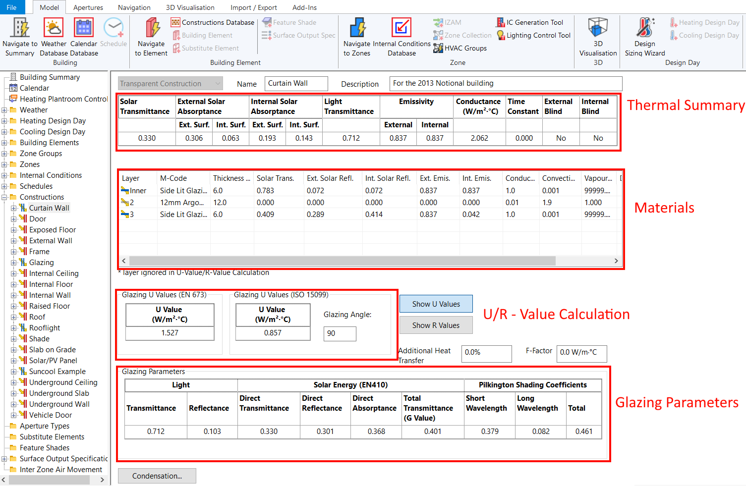
Transparent Constructions
Clicking on a transparent construction allows you to see a summary of the thermal properties of the construction, the material layers, and options for adjusting the heat transfer.
In Tas, transparent constructions have no thermal mass so the time constant is 0.
Transparent constructions should be used to model both translucent and transparent constructions.
Solar Transmittance
The solar transmittance is the fraction of solar radiation at normal incidence which is transmitted by the layer.
Solar Absorptance
Solar absorptance refers to the ratio of vertically incident solar energy that is absorbed by the construction, to the total solar energy.
Light Transmittance
The light transmittance fraction of incident visible radiation at normal incidence which is transmitted by the layer.
Emissivity
The emissivity is the amount of long wave radiation absorbed by the material, and is displayed for both the internal and external surfaces of the construction.
Conductance
The conductance is the amount of heat flux per unit temperature difference across the construction in the steady state.
The conductance applies to the construction alone and does not include the effects of surface heat transfer.
Time Constant
For transparent constructions, thermal mass is not taken into consideration so the time constant is zero.
Internal / External Blind
These properties indicate whether the innermost or outermost materials composing the transparent construction have their blind checkbox checked.
U-Values
For transparent constructions, the U-Value is calculated using two different methodologies.
EN673 is a european standard and is widely used in the United Kingdom and Europe. ISO 15099 is an international standard commonly used in the USA and for ASHRAE projects.
Note
The Building Simulator does not use the u-values as part of the simulation, and instead models the thermal properties of each material layer in detail including the effect of thermal mass. This is more accurate.
U-values represent the amount of heat transfer per degree of temperature difference across the construction, per unit area.
R-Values
The R-value is a measure of a materials ability to resist the flow of heat, and is the inverse of the U-value:
F-Factor
The F-Factor is the heat transfer through the floor due to a temperature difference between the inside and outside air temperature, per linear length of the exposed perimeter of the floor.
The F-factor should only be specified for ground floor constructions.
The exposed ground perimeter is calculated for each zone. The first ground construction that has an F-Factor will be used to calculate the perimeter heat loss for the zone.
Glazing Parameters
The glazing parameters contain a summary of derived properties of the transparent construction calculated from EN410 and from the Pilkington publication Glass and Transmission Properties of Windows (7th edition).
Light Transmittance
This is the fraction of visible radiation normal to the surface which is transmitted by the construction.
Solar Direct Transmittance
The fraction of solar radiation normal to the surface which is transmitted by the construction.
Solar Reflectance
The fraction of external solar radiation normal to the surface which is reflected by the construction.
Solar Absorptance
The fraction of external solar radiation normal to the surface which is absorbed by the construction.
Total Transmittance (G-value)
The fraction of solar radiation normal to the surface which is transferred through the construction by all means. It is composed of the Direct Transmittance and an appropriate fraction of the absorptance calculated for the assumed surface coefficients.
Shading Coefficient: Short Wavelength
The Solar Direct Transmittance divided by 0.87.
Short wave shading coefficient corresponds the percentage of solar transmission with wavelengths of 300nm to 4000nm.
Shading Coefficient: Long Wavelength
The fraction of the Solar Absorptance that is released inwards, and contributes to the Solar Total Transmittance, divided by 0.87.
Long wave shading coefficient corresponds to the percentage of solar transmission with wavelengths of 4000nm to 50000nm.
Shading Coefficient: Total
The Solar Total Transmittance divided by 0.87.
Opaque Materials
Opaque materials can be created in the constructions database and edited in the building simulator:
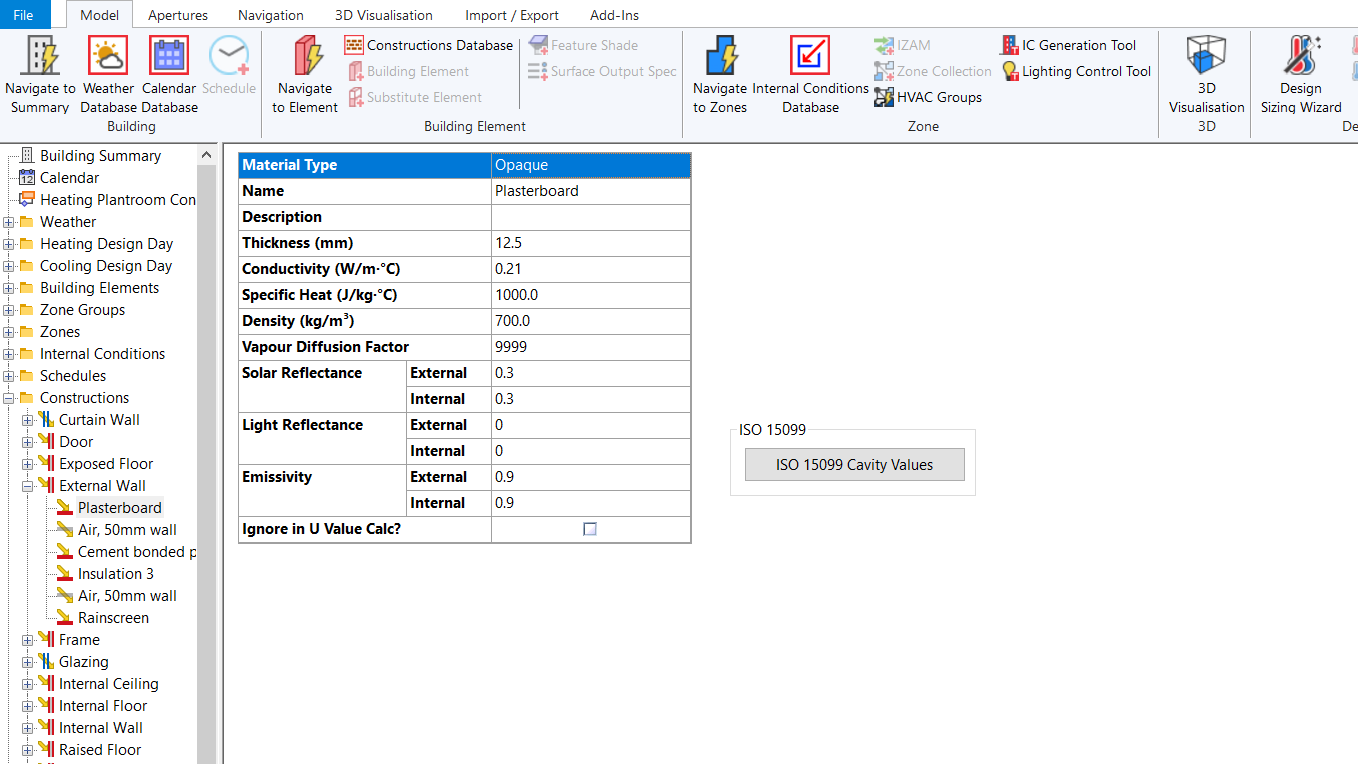
Thickness
The thickness refers to the width of the layer, and can be different to the thickness displayed in the construction view.
To edit the thickness used in the simulation for the calculation of the thermal properties, double click on the material layer in the materials table.
Conductivity
The thermal conductivity of the material layer.
Specific Heat
The specific heat capacity of the material; this field is directly related to the thermal mass of the material. The higher the specific heat capacity, the more energy is stored in the material when increasing the temperature of the material.
Solar Absorptance
The fraction of solar radiation incident on the material that is absorbed by the material.
Density
The density of the material, which is a measure of how compact the material is.
Vapour Diffusion Factor
The specific moisture diffusion resistance of the material (the ratio of the permeability of air (\(1.92e-10 kg/Ns\)) to the permeability of the material). This property is used in interstitial condensation calculations.
External Solar Reflectance
The fraction of external solar radiation at normal incidence which is reflected by the layer.
Internal Solar Reflectance
The fraction of internal solar radiation at normal incidence which is reflected by the layer. This will differ from the External Solar Reflectance if the layer is asymmetrical.
External Light Reflectance
The fraction of external visible radiation at normal incidence which is reflected by the layer.
Internal Light Reflectance
The fraction of internal visible radiation at normal incidence which is reflected by the layer.
External Emissivity
The fraction of external incident long-wave radiation which is absorbed by the material (or, equivalently, its efficiency as a radiator of thermal radiation, expressed as a fraction of the efficiency of a black body radiator at the same temperature).
Internal Emissivity
The fraction of internal incident long-wave radiation which is absorbed by the material (or, equivalently, its efficiency as a radiator of thermal radiation, expressed as a fraction of the efficiency of a black body radiator at the same temperature). This will differ from the External Emissivity if the layer is asymmetrical.
Transparent Materials
Transparent materials can be created in the constructions database and edited in the building simulator:
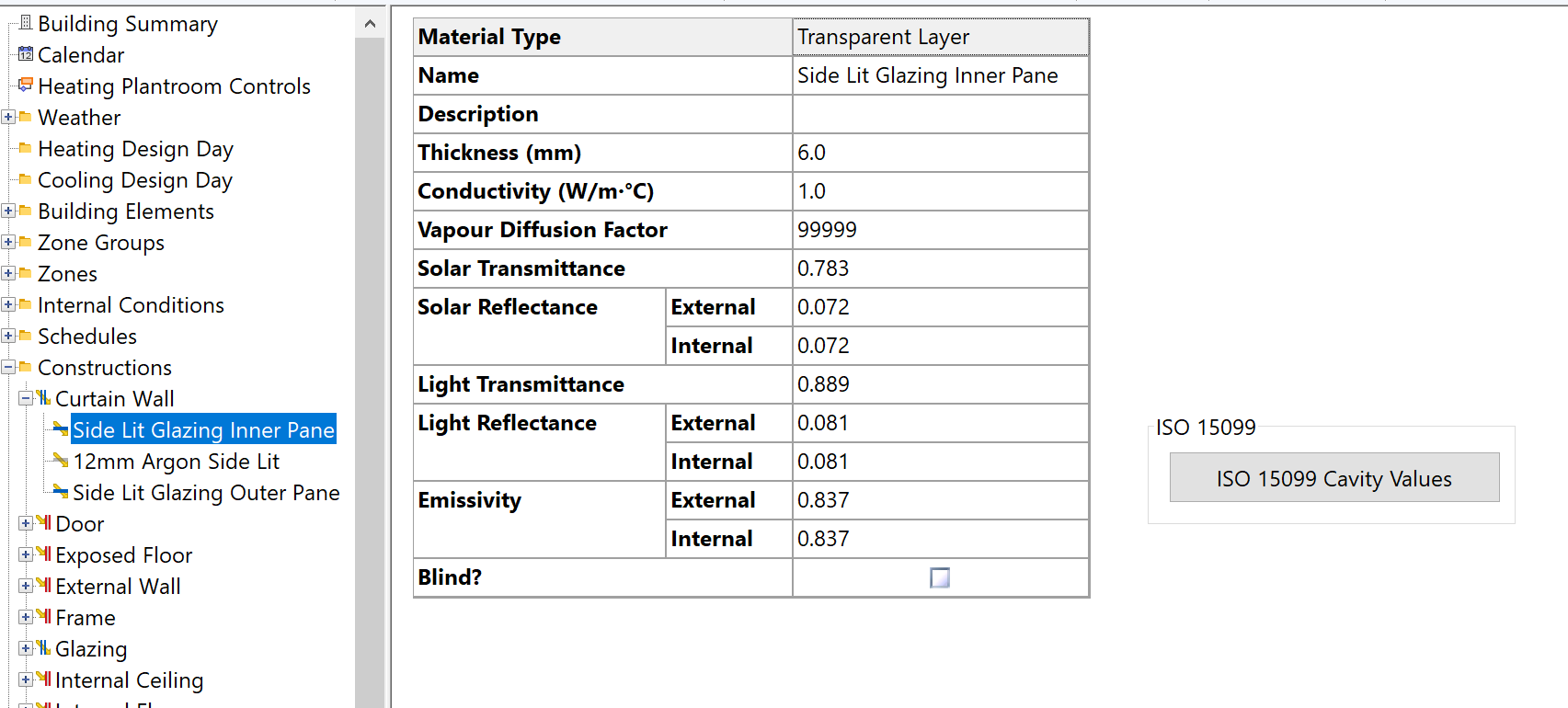
Width
The width of the layer. Unlike with the width of opaque materials, the value here directly affects the width in the overall transparent construction.
Conductivity
The thermal conductivity of the material.
Vapour Diffusion Factor
The specific moisture diffusion resistance of the material (the ratio of the permeability of air (\(1.92e-10 kg/Ns\)) to the permeability of the material). This parameter is used in interstitial condensation calculations.
Solar Transmittance
The fraction of solar radiation at normal incidence which is transmitted by the layer.
External Solar Reflectance
The fraction of external solar radiation at normal incidence which is reflected by the layer.
Internal Solar Reflectance
The fraction of internal solar radiation at normal incidence which is reflected by the layer. This will differ from the External Solar Reflectance if the layer is unsymmetrical (for instance a glass pane with a metallic coating on one side).
Light Transmittance
The fraction of incident visible radiation at normal incidence which is transmitted by the layer.
External Light Reflectance
The fraction of external visible radiation at normal incidence which is reflected by the layer.
Internal Light Reflectance
The fraction of internal visible radiation at normal incidence which is reflected by the layer.
External Emissivity
The fraction of external long-wave radiation which is absorbed by the layer.
Internal Emissivity
The fraction of internal long-wave radiation which is absorbed by the layer. This will differ from the External Emissivity if the layer is unsymmetrical.
Blind Checkbox
Check the box if the layer is a blind, otherwise the box should be unchecked. This affects the treatment of convection, both in Tas and in the calculation of CIBSE and Pilkington parameters.
In the calculation of Pilkington parameters, convection coefficients for gas layers adjacent to blinds are automatically increased by a factor 4/3 to allow for the effects of convection currents in the larger gas space enclosing the blind.
The same procedure is adopted in Tas, where it is extended to the treatment of convection heat exchange between an internal blind and the room air. Here a convection coefficient of 4/3 the usual value is applied. (This contrasts with the treatment in CIBSE and Pilkington procedures where the blind is tacitly assumed to be at room temperature, implying an infinite convective heat transfer coefficient.)
Gas Layers
Gas Layers can be created in the constructions database and edited in the building simulator:
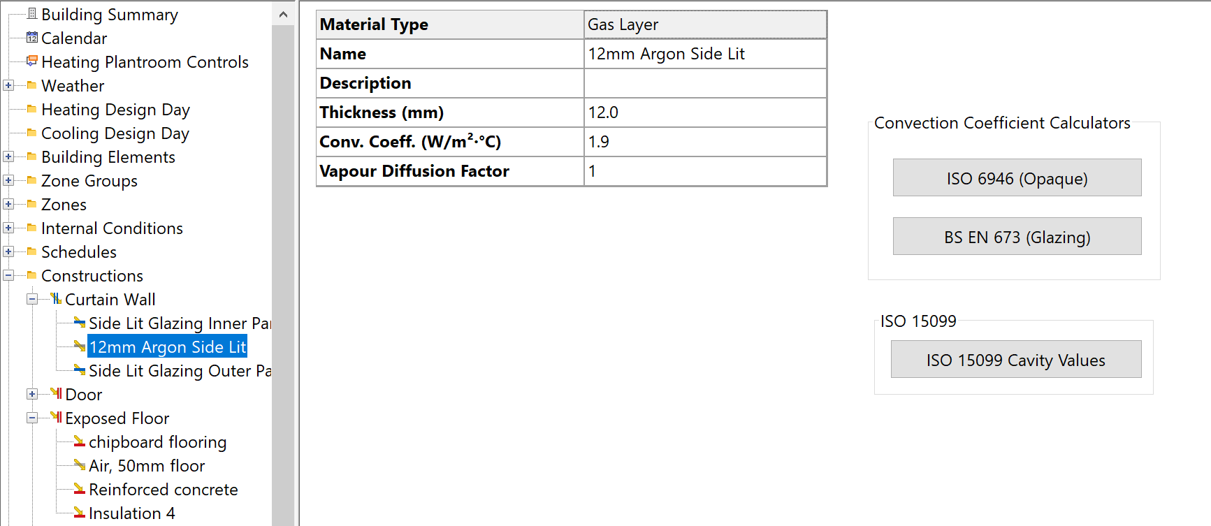
Gas layers can be added to both opaque and transparent constructions.
Width
The width of the layer, as it appears in the construction.
Convection Coefficient
The heat transfer coefficient for convective heat transfer across the layer. If the gas layer is adjacent to a blind, the convection coefficient is automatically increased by a factor 4/3.
Values of the Convection Coefficient may be calculated for gas cavities of various dimensions and orientations using the built in convection coefficient calculators in Tas.
The convection coefficient calculators automate the following calculation:
Calculate the dimensionless quantity GrPr (the product of the Grashof and Prandtl numbers) using:
\(A\) = \(1.241e8\) for dry air/ \(1.433e8\) for argon/ \(4.607e9\) = width of the cavity, in meters. \(\Delta T\) = mean temperature difference across the cavity.
2.) Calculate the dimensionless Nusselt Number \(\text{Nu}\) using:
\(h\) = the height of the cavity. In the case of horizontal heat flow (vertically oriented cavity), \(C\), \(n\) and \(m\) are assigned values from the following table:
Heat Flow Horizontal |
GrPr |
C |
n |
m |
|---|---|---|---|---|
Up |
<200000 |
0.197 |
1/4 |
-1/9 |
Up |
>200000 |
0.073 |
1/3 |
-1/9 |
Up |
<7000 |
0.059 |
2/5 |
0 |
Up |
7000<GrPr<320000 |
0.212 |
1/4 |
0 |
Up |
>320000 |
0.061 |
1/3 |
0 |
Down |
1.000 |
0 |
0 |
If \(Nu\) is less than 1.0, set \(Nu = 1.0\).
Calculate the heat transfer coefficient (\(W/m^2K\)):
\(\lambda\) = thermal conductivity of the gas (\(W/mK). :math:\) for dry air, 0.0168 for argon, 0.0128 for sulphur hexaflouride.
Vapour Diffusion Factor
The specific moisture diffusion resistance of the material (the ratio of the permeability of air (\(1.92e-10 kg/Ns\)) to the permeability of the material).