Zones
The Zones Table
The Zones folder shows a list of all zones which have been assigned in the 3d Modeller.
At the point of export from the 3D Modeller each zone is automatically numbered, and that zone number is then used throughout the remainder of the software as an additional refence for the zone.
The Zones folder list view shows a summary of all attributes for each zone:
The description applied in 3d Modeller, which can also be added in the tbd.
Floor area (\(m^2\))
Volume (\(m^3\))
No. of surfaces
Internal Condition applied
Any IZAMs (Inter Zone Air Movements) applied
The Convection Coefficient for the zone
Daylight Factor
Heating & Cooling Sizes
Output toggle
Zone Details
Description
The description given for the zone either in the 3D Modeller or which can be added here in the tbd.
Floor Area
The floor area for the space is measured as the net internal area, i.e. measured from the inside face of each wall.
Warning
Note that this is not necessarily the same thing as the area of the floor surface used for heat loss calculations.
Volume
Volume is measured based on the internal height from the finished floor to ceiling finish, multiplied by the floor area as defined above.
No. of Surfaces
Typically a cube will have 6 surfaces - the floor, ceiling and 4 walls. However when considering a cube shaped room, one of the walls may border two adjacent zones meaning that wall is split into 2 ‘surfaces’. This principle could also be applied to the floor or ceiling. Additionally a wall may contain a window, and that window may comprise an upper and a lower part, each part will comprise a pane and a frame, and every one of these elements will count as a surface in Tas. Each individual surface will be considered when the building simulates with the thermal properties of each surface being considered, and that simulation data can be made available for any individual surface after simulation. It is a good idea to try to keep the total number of surfaces in any zone below around 100 if possible.
Internal Conditions
Internal Conditions (ICs) describe a profile of what happens in any given space, including schedules, internal gains, thermostats and so on. Internal Conditions must be assigned to zones to describe how they behave. See the Internal Conditions section for more information.
IZAMs
IZAM stands for Inter Zone Air Movement and describes forced ventilation flow paths through a zone. This can include air into a space from outside, out of a zone from inside, or from one zone to another. IZAMs should not be used to represent a simple exchange with outside air which can be modelled in an internal condition. They do need to be used when supply air is tempered to a particular set-point or to model a specific flow network.
Convection Coefficient
By defalt Tas will calculate the Convection Coefficient for each surface in a zone based on the surface to air temperature difference and the room geometry, and hence this field will read default. You can type in your own Convection Coefficient here and it will be applied to all zone surfaces (except nulls).
Daylight Factor
The daylight factor will read 0 by default. You can type in a Daylight Factor for each zone here in the tbd, or use Tools > Calculate BRE Daylight Factors to use a very simple tool to automatically calculate the Daylight Factors and populate the zones. The recommended option would be to use the Daylighting tool integrated in the Tas 3d Modeller. When using this tool the Daylight Factors will be simulated accurately and output when the 3D model is exported, automatically populating the Daylight Factor fields.
A daylight factor is required if the zone is to use daylight linked lighting controls which can be set up either in the Internal Condition or by using the Lighting Control Tool.
See also BRE Daylight Factors
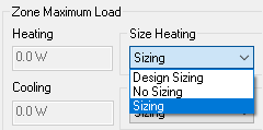
Zone Maximum Loads
These fields specify the maximum heating & cooling energy (measured in Watts) available within a zone, which can be used to maintain the heating & cooling set-points. These values can ve manually set or can be calculated by the software:
Sizing This is the default option, and when set to Sizing Tas will calculate the peak energy requirement during simulation and report the result in these fields.
Design Sizing Tas will run any heating or cooling Design Days which have been set up in the tbd and calculate the maximum heating or cooling loads based on those design days, and report the values in the ‘Zone Maximum Load’ fields. This will now be the maximum capcaity available for heating and cooling when runnig the dynamic simulation.
No Sizing Means that Tas will not attempt to size the heating or cooling requirement, but instead will use the value typed into the field by the user. This allows you to enter, for example, the radiator sizes for the zone then simulate and see whether setpoints are maintained.
Internal Conditions, IZAMs and Surface Output Specifications can be removed from the Zones List by right clicking a zone and selecting ‘remove…’ Attributes can also be removed from zones by going to the Zone details page, selecting the attribute and selecting Delete on the keyboard.