Analysis Model
In order to use a 3D model for analysis, an analysis model needs to be created.
An analysis model verifies the integrity of the inputted geometry and ensures:
There are no unintentional ‘gaps’
Planes are ‘physical’ (realistic)
Windows are contained within walls
No overlapping geometry
The analysis model also contains information about surfaces such as:
Other surfaces they are linked to
Volume calculations
Area calculations
and can be used to perform:
Shadow calculations
Daylight calculations
The analysis model can also be exported to the Building Simulator, for thermal analysis.
Note
You should always visually inspect the analysis model, as this represents the geometry that will be used for building analysis.
Creating
To create an analysis model, first select a 3D view.
Then go to Model >> Analysis Model >> Show in the ribbon:
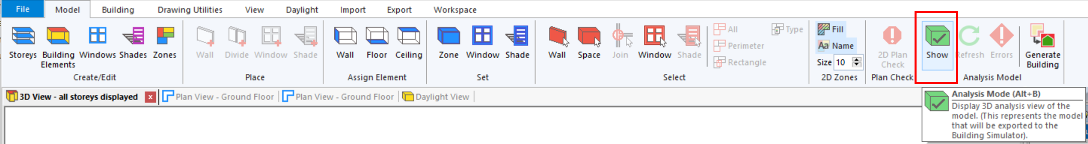
If there are any problems or potential problems with the model, the errors and warnings dialog will appear.
You can click the Show button again to toggle between the 3D view and analysis model.
Refreshing
If you change the geometry in the model when an analysis model has already been created, you will need to update the analysis model by pressing the Refresh button.
This is very important, as daylight analysis and shadow calculations will be performed on the current analysis model.
Warning
You must refresh the analysis model after making changes to the geometry before performing daylight calculations.
To refresh the analysis model, go to Model >> Analysis Model >> Refresh in the ribbon.
Exporting
You can export the analysis model to the Building Simulator via Model >> Analysis Model >> Generate Building in the ribbon:
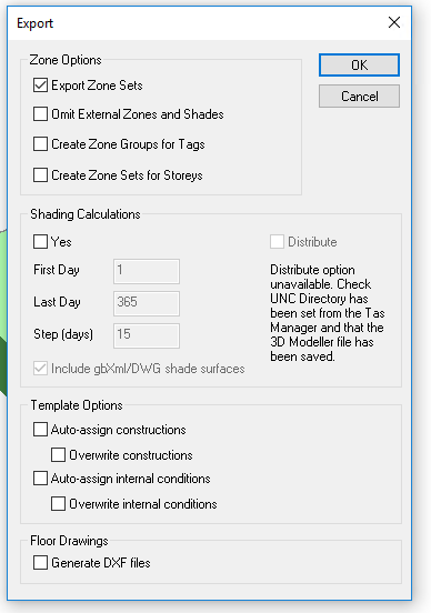
The export dialog contains a number of options that allow you to control the information that is exported to the Builidng Simulator.
Export Zone Sets
The Export Zone Sets option creates zone sets in the Building Simulator that match those in the Zones dialog in the Tas3D file:
Only zones that are used will be exported.
Omit External Zones and Shades
This option prevents any zones with the external checkbox applied from being output to the Building Simulator.
As shades are applied to external zones, if this option is checked, the shades will not appear in the Building Simulator either.
This option also excludes external zones and shades from the shading calculations.
Warning
If you add a shade to an unzoned space and export to the Building Simulator, the direct shading will be accounted for in the shading calculations but the shade will not appear in the Building Simulator.
Create Zone Groups for Tags
Checking this option ensures a new Zone Group will be created for each Tag in the Zones Dialog that has been applied to at least one used zone:
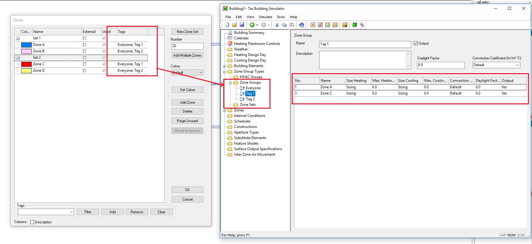
Zones can have any number of tags applied.
Create Zone Sets For Storeys
As with Create Zone Groups for Tags, this option ensures a Zone Group is created containing each used zone for each Storey.
Shading Calculations
You can enable Shading Calculations by checking the corresponding checkbox. Without shading calculations, you will not be able to simulate your Building Simulator file.
For large models, you may wish to export without shading calculations in order to work on the constructions & internal conditions etc, and then export the shading calculations at a later time.
You can distribute the shading calculations to other computers on your network which have Tas installed and licensed.
Template Options
If you used the Create Building wizard in the Tas Manager to setup your project and create your initial Tas3D file, these options will apply:
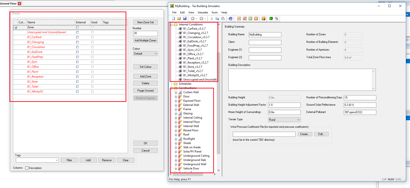
The Create Building wizard automatically creates a Tas3D and Building Simulator file with:
Zone Sets
Constructions
Weather file
Internal conditions
These are based on the template file which is selected when using the wizard.
The options in the export dialog allow you to choose whether the 3D modeller automatically assigns internal conditions based on the zone sets the zones are in, and also automatically assigns Constructions based on the Building Element names.
The Exported Model
The exported model is composed of a number of zones.
Each zone has surfaces which can link to other surfaces or be exposed to the outside.
Each surface also has a Building Element
Viewing
In the 3D modeller, there are a number of view options that apply specifically to the analysis model.
These options are quite helpful when visually inspecting the model to verify correctness.
You can filter the 3D analysis model by:
Zone
Storey
You can also choose to colour the model by:
Building Element
Zone
The nature of the surface (exposed, adiabatic, internal etc..)