Pitches & Planes
In the 3D modeller, floors and ceilings can have a slope applied. We refer to the these slopes/pitches as planes.
There are a number of ways to create and apply planes in the 3D modeller:
Adjusting wall heights
Adjusting join heights
Creating a 3D plane & applying it via the select tools
For simple slopes, the easiest way to create a pitched roof/floor is by adjusting the wall or join heights.
For more complex slopes where you may wish to apply the same plane to a number of surfaces, the 3rd option is best as you can save the plane for use on multiple ceiling/floor elements.
Note
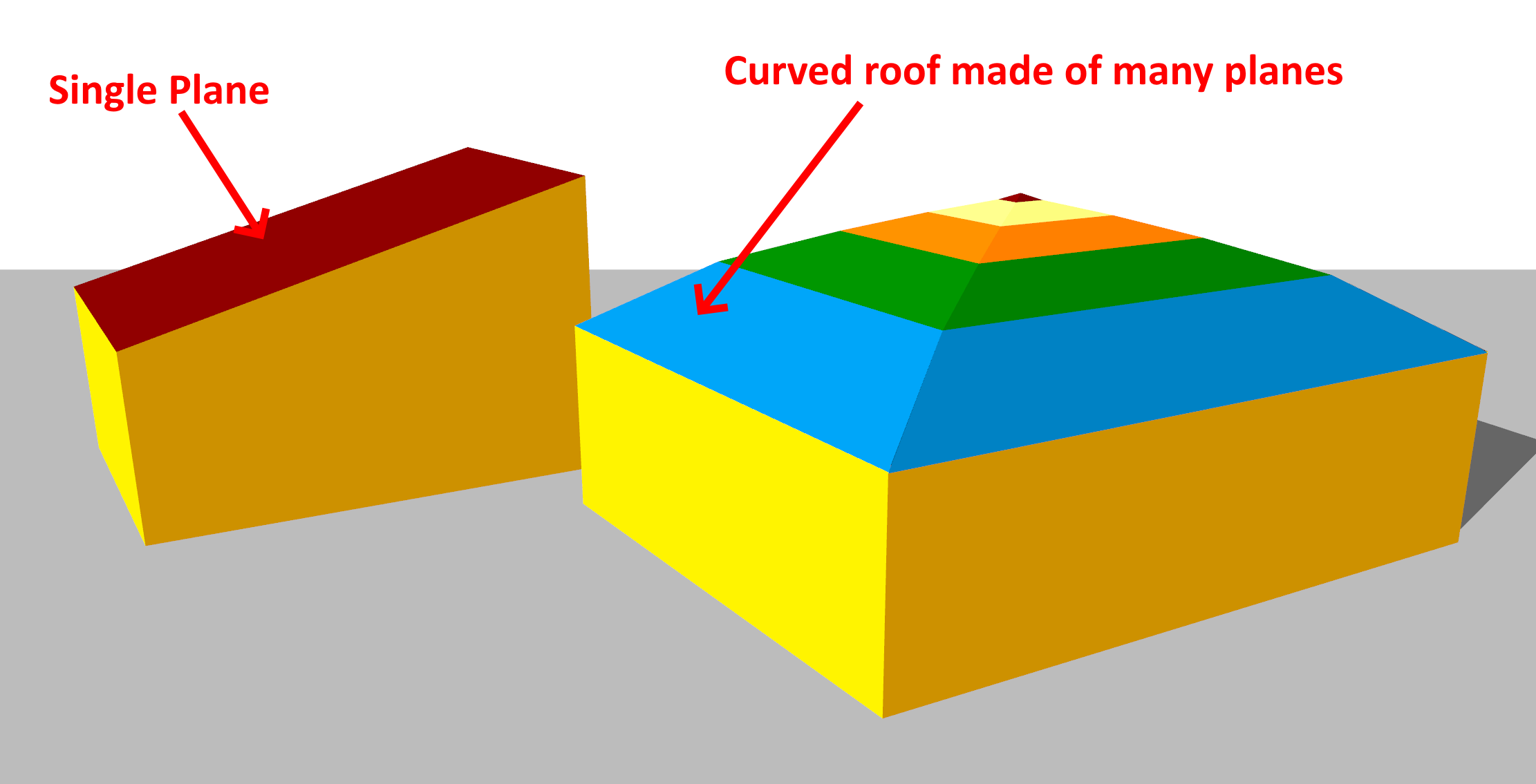
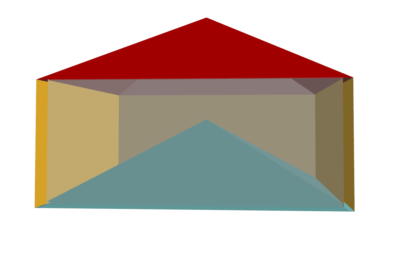
All slopes in the 3D modeller must be planar.
This essentially means slopes must be ‘flat’. If you want to create a curved roof, you’ll need to use a number of flat planes to achieve the effect:
Adjusting Wall Heights
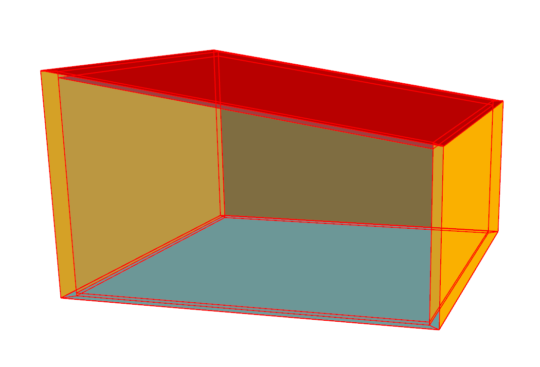
A simple way of creating a sloped roof is to adjust the height of one or more of the walls that makes up a space:
To do this, use the select wall tool in the model section of the ribbon. Right click on the selected wall, and select height.
This results in the entire roof element being sloped:
If you wanted to create a suspended ceiling, you would need to create another Storey above the current floor.
You can also set the floor height in the same way:
If you change the height of walls in the middle of a space, the 3D modeller will automatically apply multiple planes to achieve the desired effect:
Adjusting Join Heights
Another simple way to create sloped surfaces is to adjust the height of a join:
To do this, use the select join tool in the model section of the ribbon.
You can also slope floors in the same way:
Creating Planes
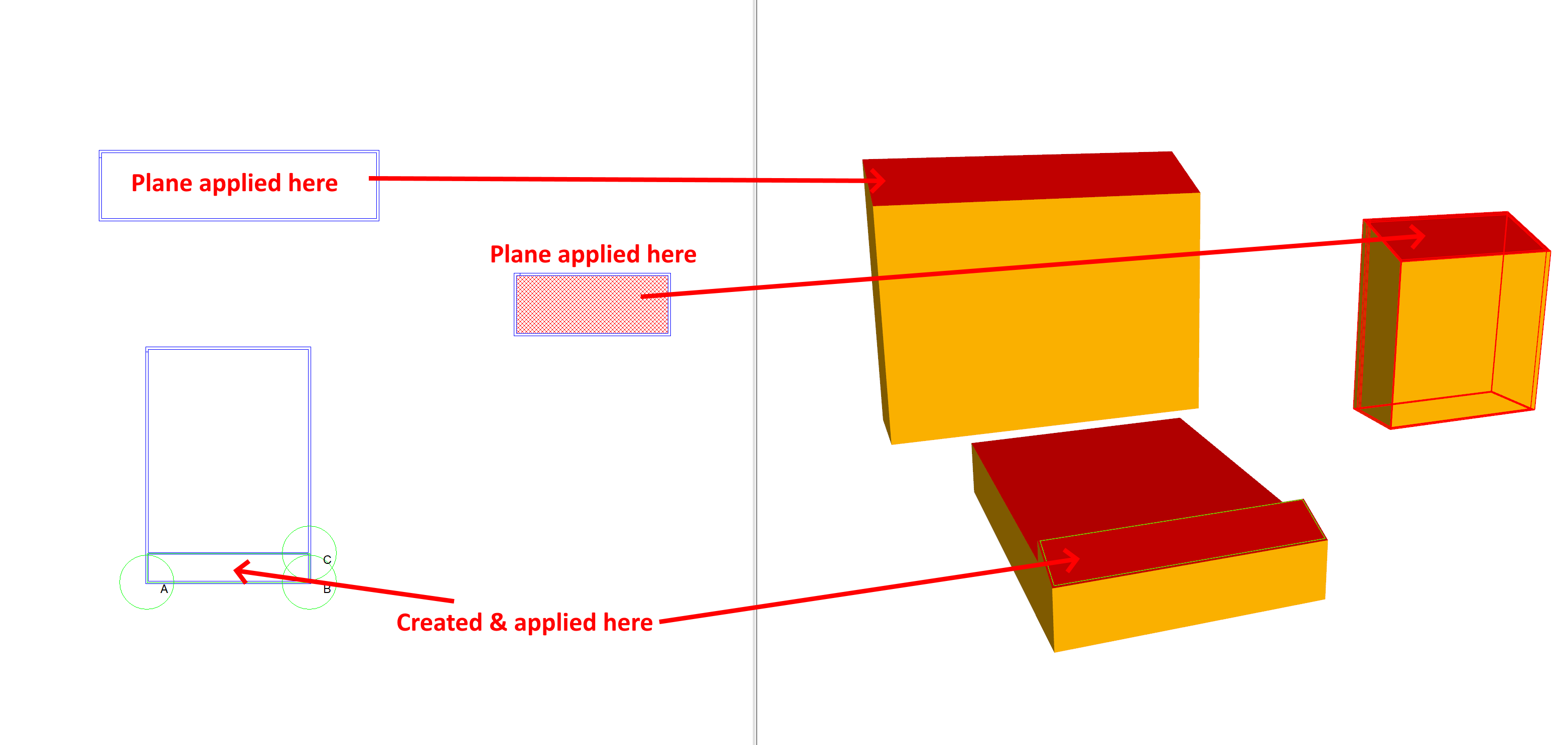
You can also create planes in a more explicit way. These planes can then be applied to any number of surfaces, and extend throughout the 3D model:
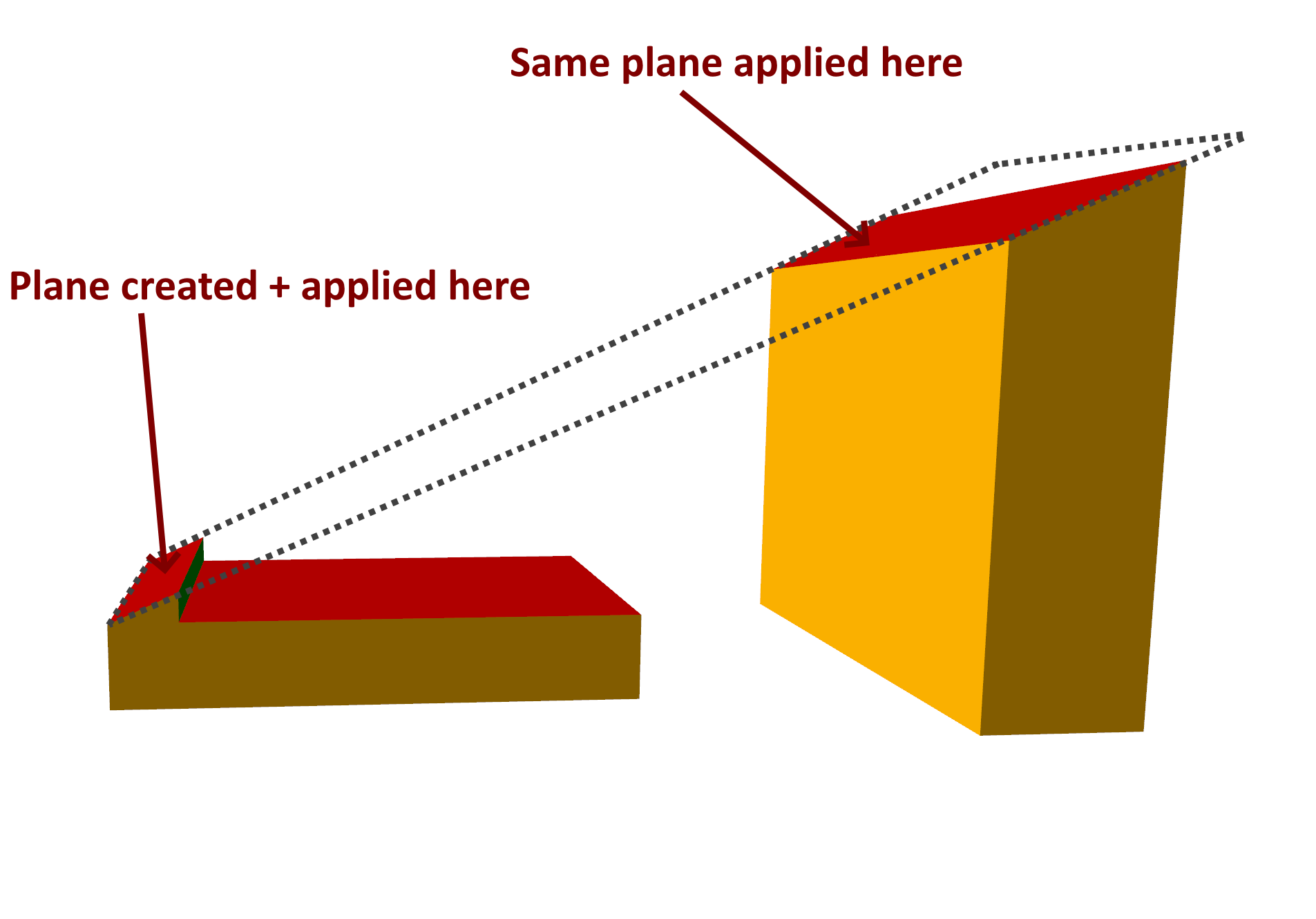
In the above, one plane was created and applied to two different ceiling elements. The dotted grey line illustrates how the plane extends. It can also extend horizontally:
There are several ways to define a new plane:
By Points
By Offset
By Inclination
By 3D surfaces
By Points
To create a plane by points, first use the select join tool to select 3 joins that lay on the desired plane.
Note
To select multiple joins, hold the ctrl key on the keyboard when clicking.
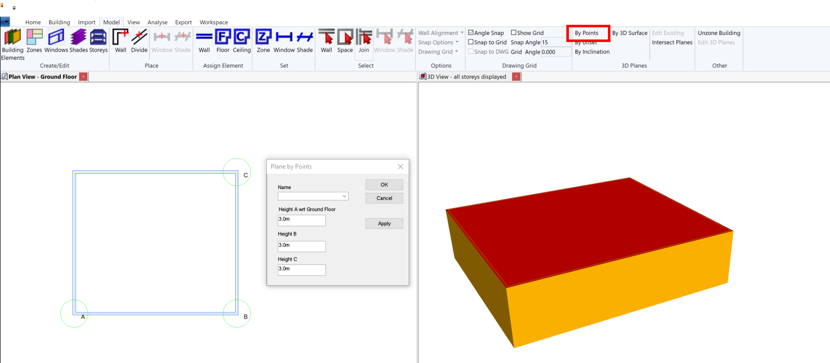
You can then specify the heights of those points on the new plane, and give the plane a name.
By Offset
If you already have a saved plane, you can create another plane with the same inclination as the saved plane, but with a different offset:
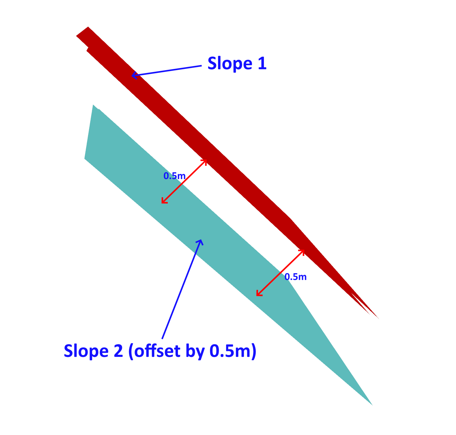
Here, both the floor and the ceiling elements have planes applied. One is offset perpendicular to the other.
Creating a plane by offset is very useful when drawing PV panels.
To create a plane by offset, click model >> 3D Planes >> By offset in the ribbon:
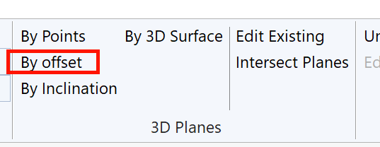
You can then select the plane you wish to create an offset plane from, and enter the perpendicular offset distance:
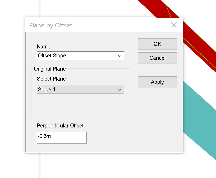
The perpendicular offset can be positive or negative.
By Inclination
If you are trying to create a plane with a very specific inclination (angle), you can specify the angle directly rather than having to work out which join/wall heights will achieve that angle.
To create a wall by inclination, first select a wall using the select wall tool.
Then press the By Inclination button in the 3D Planes section of the ribbon:
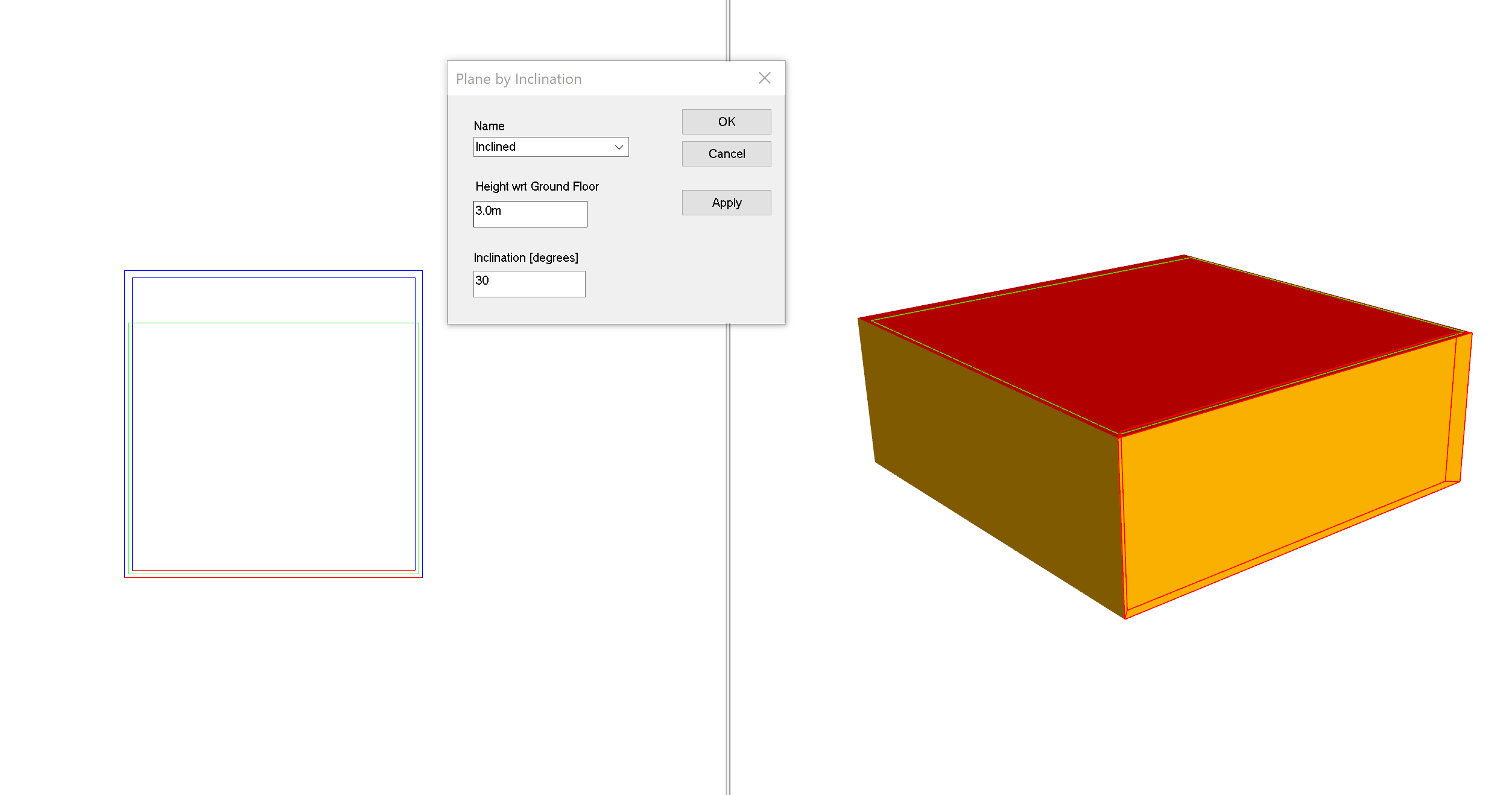
The height wrt (with-respect-to) box corresponds to the relative height at which the plane should start:
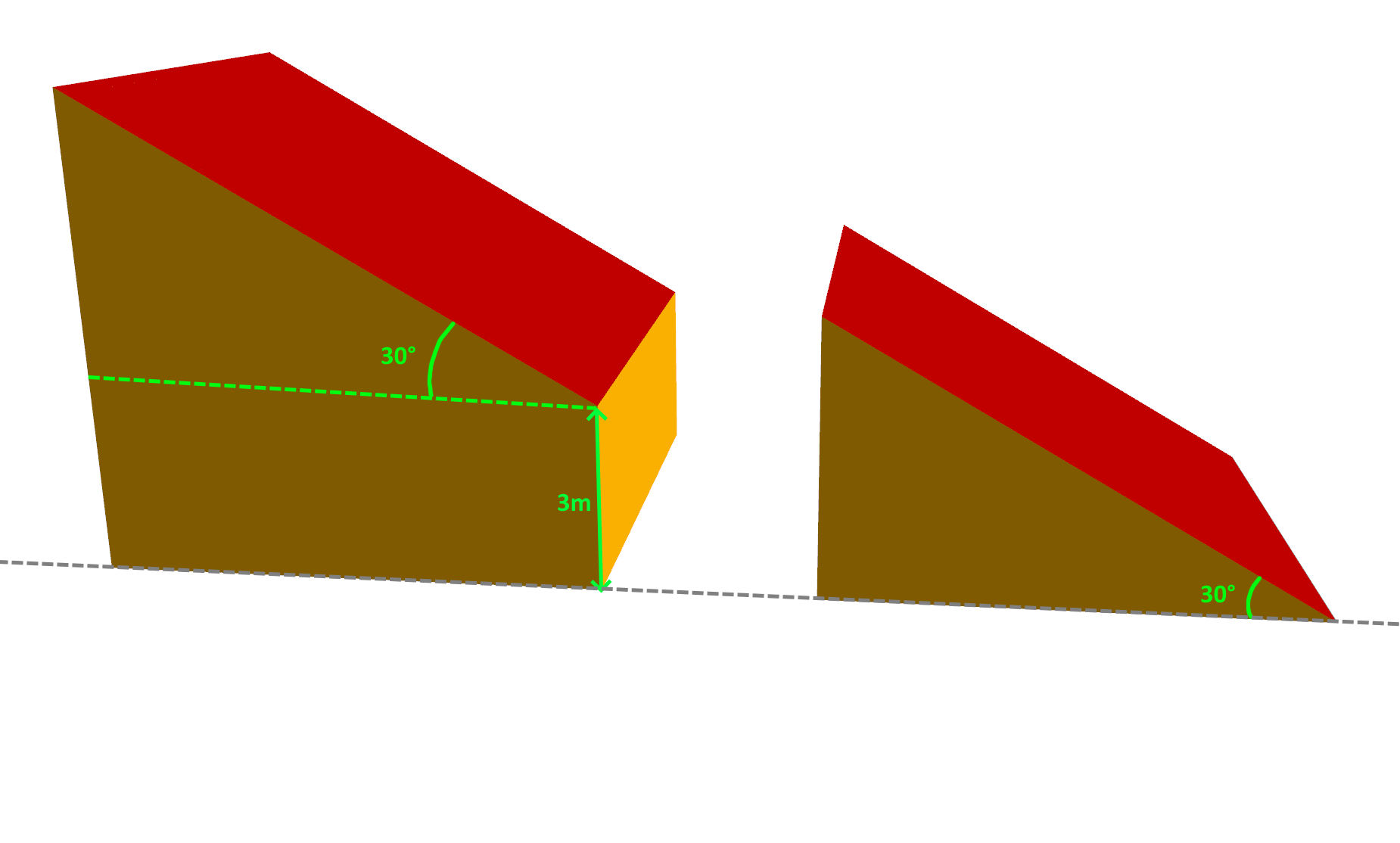
The left space has a height with respect to the ground storey of 3m, whereas the right space has a ceiling with the height set to 0m. Both have an angle of 30°.
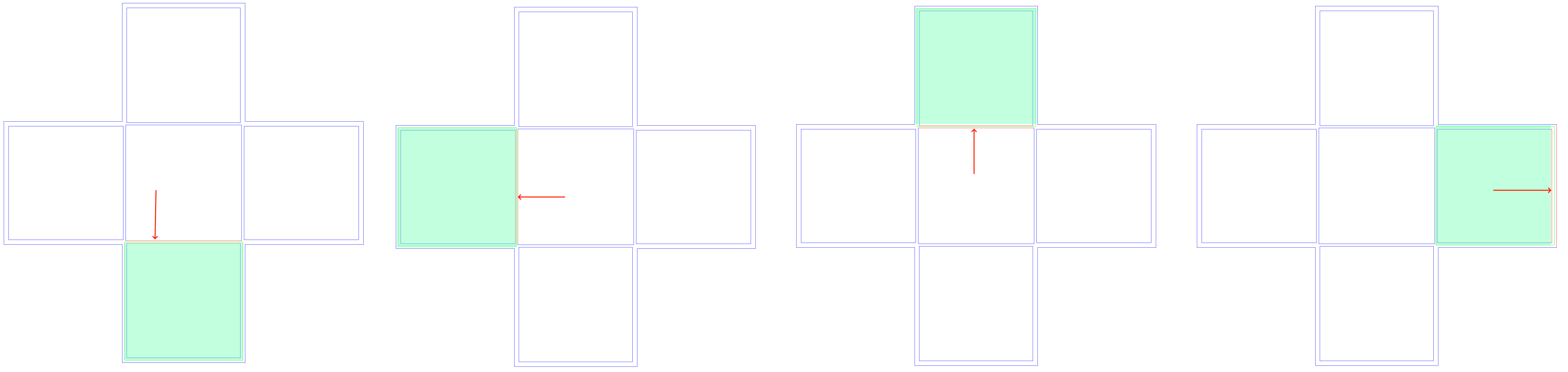
The direction the plane extends in is determined by the orientation of the selected wall when the by inclination button is pressed:
By 3D Surface
If you have imported 3D geometry from a gbXML model or a 3D DWG, you can create a plane from that imported geometry.
This is useful when you wish to create a plane with the same properties as an imported one.
To create a plane by 3D surface, use the select space tool in a 3D view:
Applying Planes
Once you’ve created a 3D plane, you can apply it to the ceiling or floor of a space using the select space tool.
First, select the space, then right click and select height:
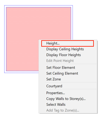
You can then apply the plane to the ceiling via the Ceiling Height tab:
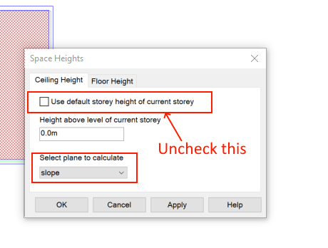
The same applies to the Floor Height tab.
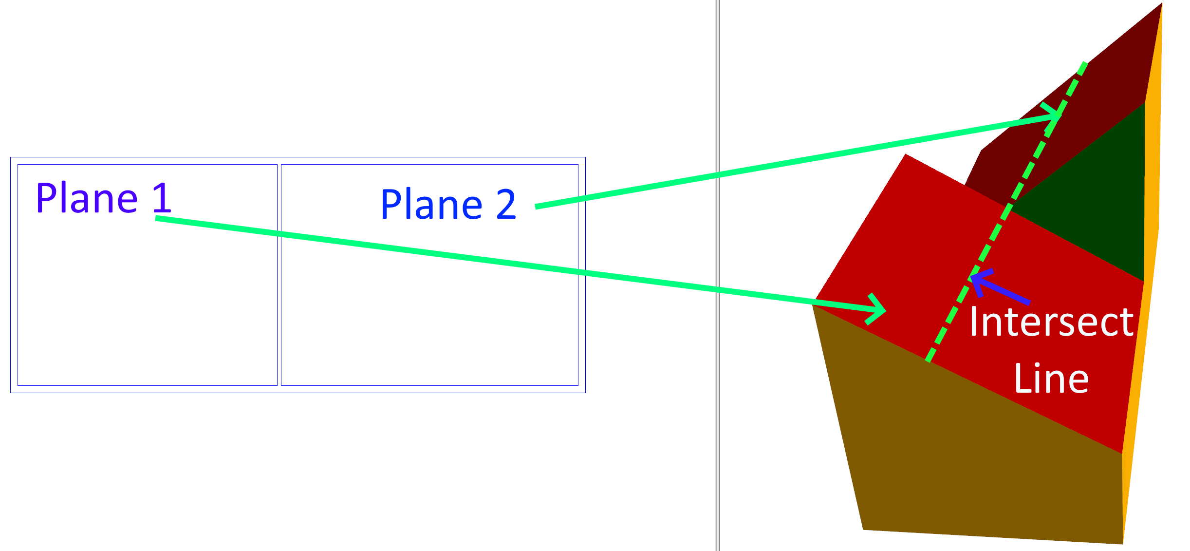
Intersect Planes
The Intersect Planes option draws null walls at the point where two planes would meet:
After using the intersect planes option:
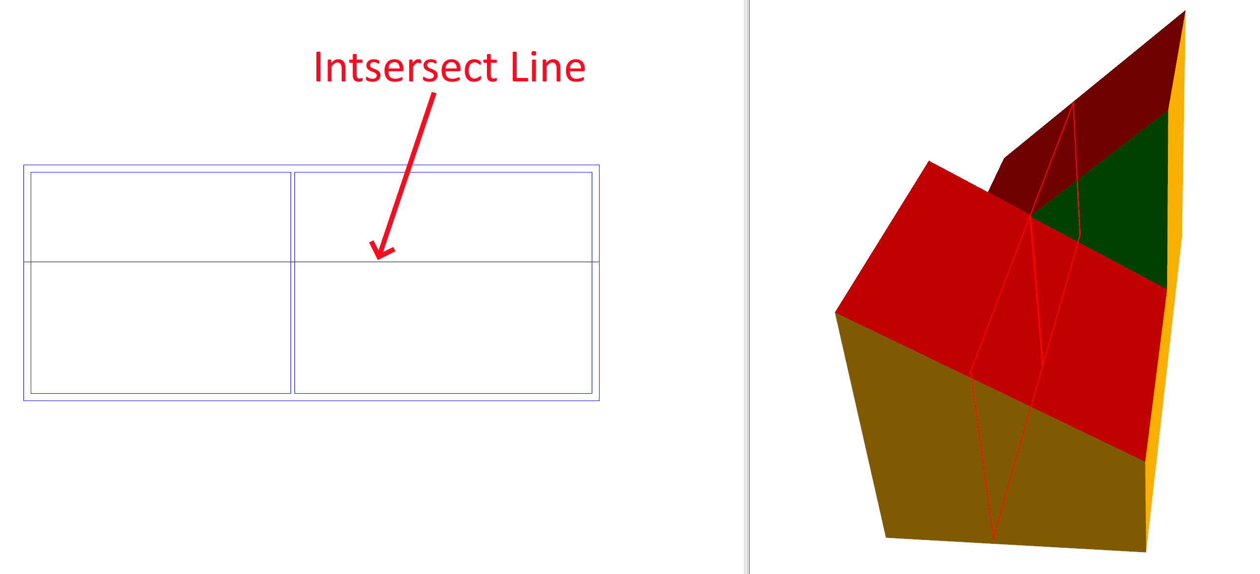
You can see the null wall has been automatically created representing the intersection point.
To use this tool, select two spaces which have a plane applied and click intersect planes:
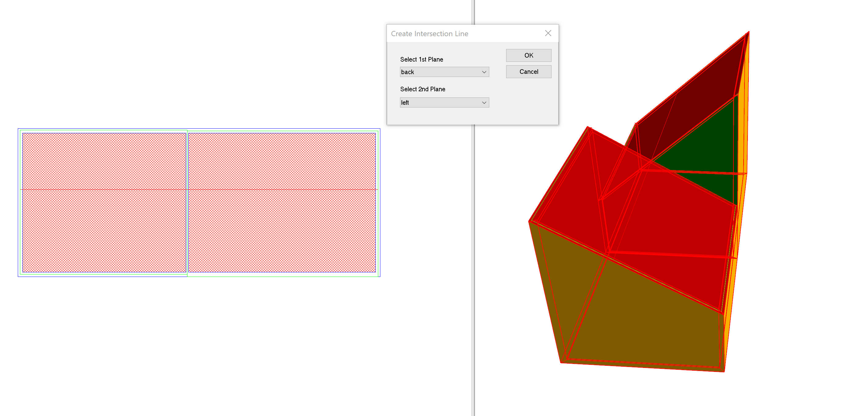
Select the two planes you wish to intersect and press ok. The intersection null will be created on the selected places where the intersection occurs.
The intersect planes option is very useful when creating dormer windows. For more information, see Dormer Windows.