3D Shade Surfaces
A 3D DWG file containing 3D geometry can be imported to represent additional shading to a model. For example, the 3D geometry can represent surrounding buildings or complex shading systems that cannot be modelled within the 3D modeller. These shading surfaces are then included in shading calculations for the Building Simulator and in Daylight calculations.
Pre-requisites
It is usually easier to import the DWG as a CAD Drawing first, to ensure the 3D surfaces are added in the correct place. This applies if the surfaces are to be added to an existing building model. Geometry can be imported into a new model before walls have been created. In this case the units in the drawing must be correct. This method can then help with wall placement - see below.
Note
If the view in the DWG file is not a plan view, a “top down” view is displayed to set the scale and mapping when importing the file using Import >> Drawings >> CAD
Drawing Scale and Model Mapping
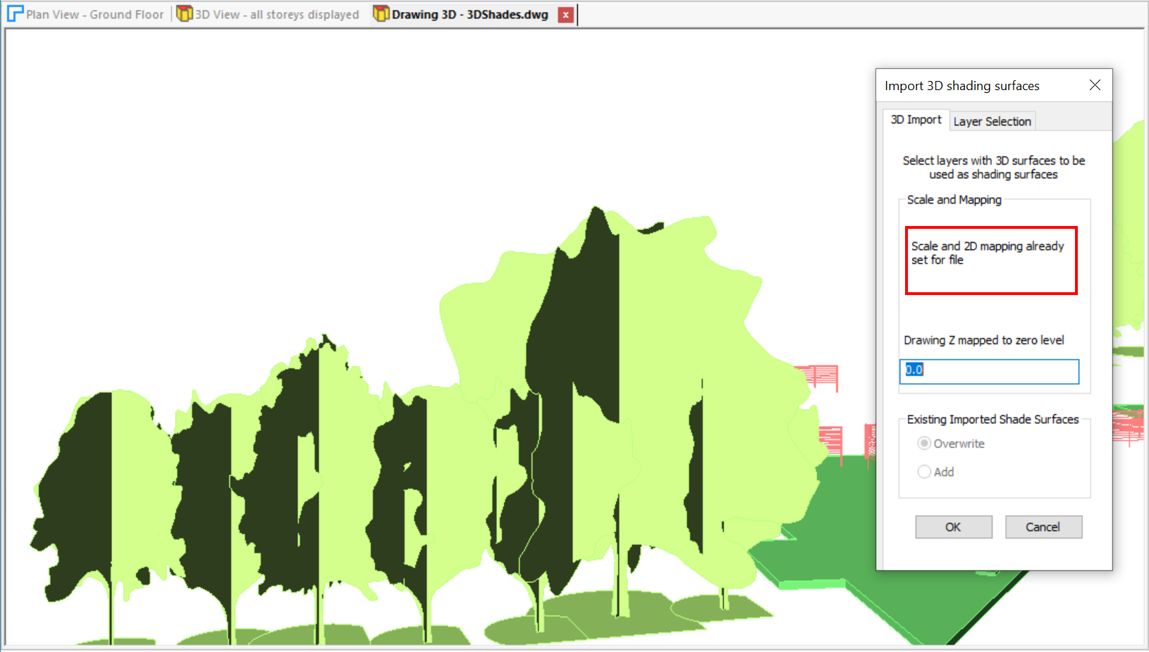
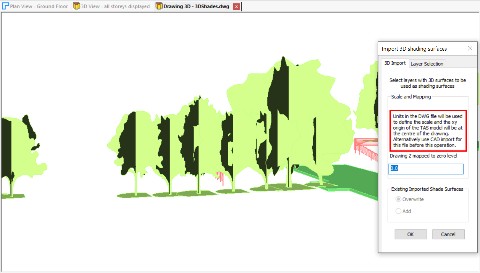
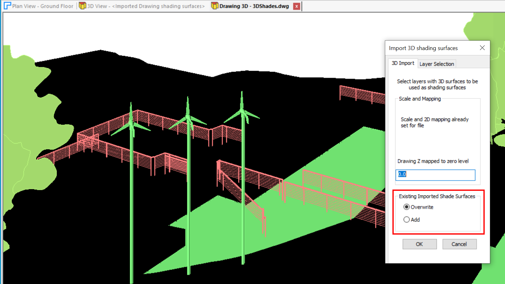
Go to Import >> 3D DWG to select a file. The Import 3D shading surfaces dialog and a 3D View of the surfaces in the DWG file is displayed.
If the DWG file has previously been imported using Import >> Drawings >> CAD, it is assumed that the scale and 2D mapping have already been set.
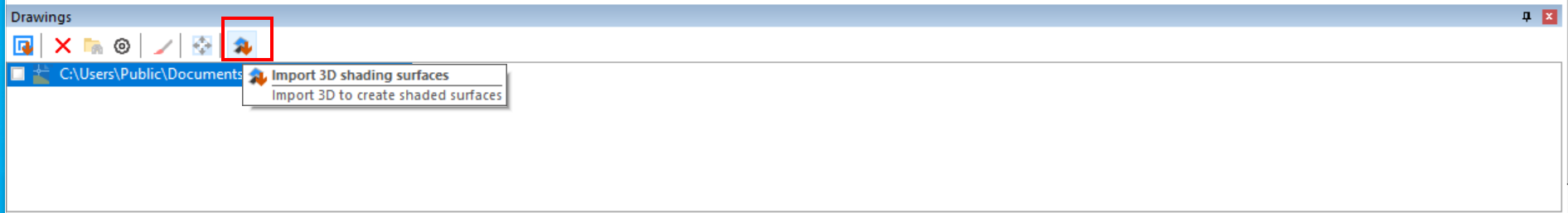
Alternatively there is an option on the Drawings Sidebar which shows the same dialog.
Note
View >> Pan/Zoom options, View >> 3D Camera >> Orbit option and View >> 3D View Presets options can be used to manipulate the Drawing 3D view.
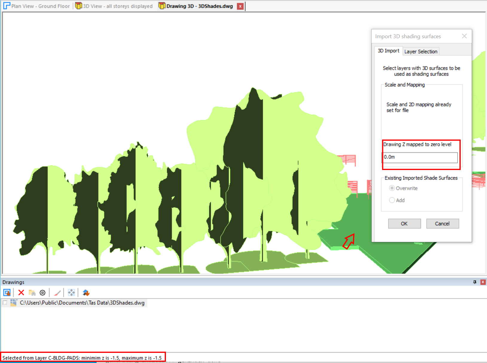
The z location of the imported surfaces may need to be adjusted if the storey levels in the 3D Modeller do not match the position of the shade surfaces. To facilitate this and to check the z position of the surfaces as displayed, clicking on a surface in the Drawing 3D view displays its layer and z range.
If walls have not yet been placed using the 3D Modeller and the DWG file has not been imported as a CAD file, the units in the DWG file are used to define the scale. The xy origin of the walls created in the 3D Modeller will be at the centre of a top view of the DWG file.
Layer Selection
All the layers are initially shown.
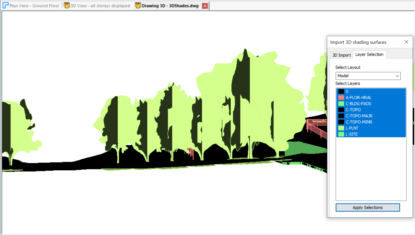
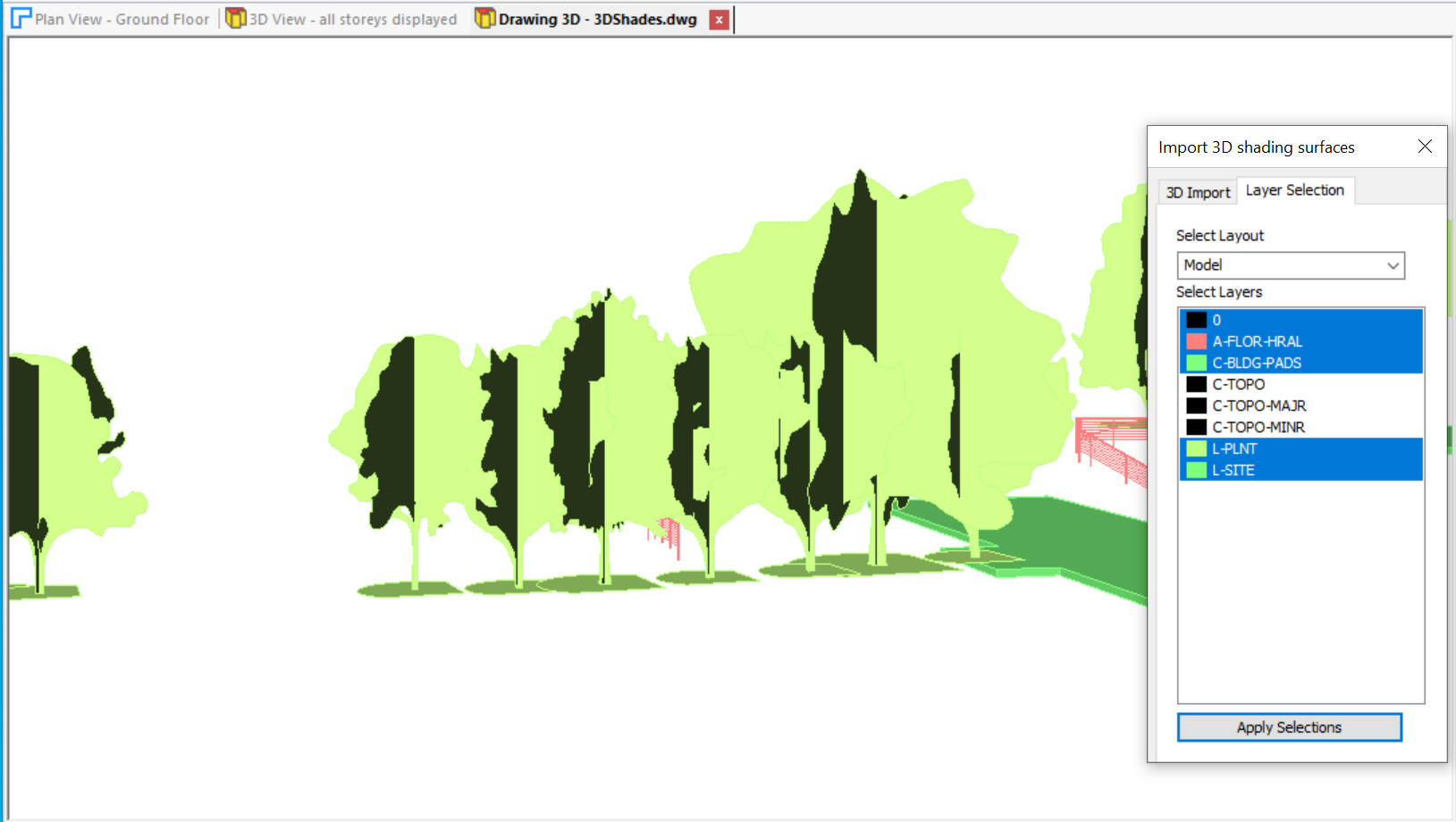
Select the layers from which the 3D surfaces will be extracted.
Note
It is possible to add further 3D surfaces from omitted layers in a subsequent operation by selecting the Add option. See below.
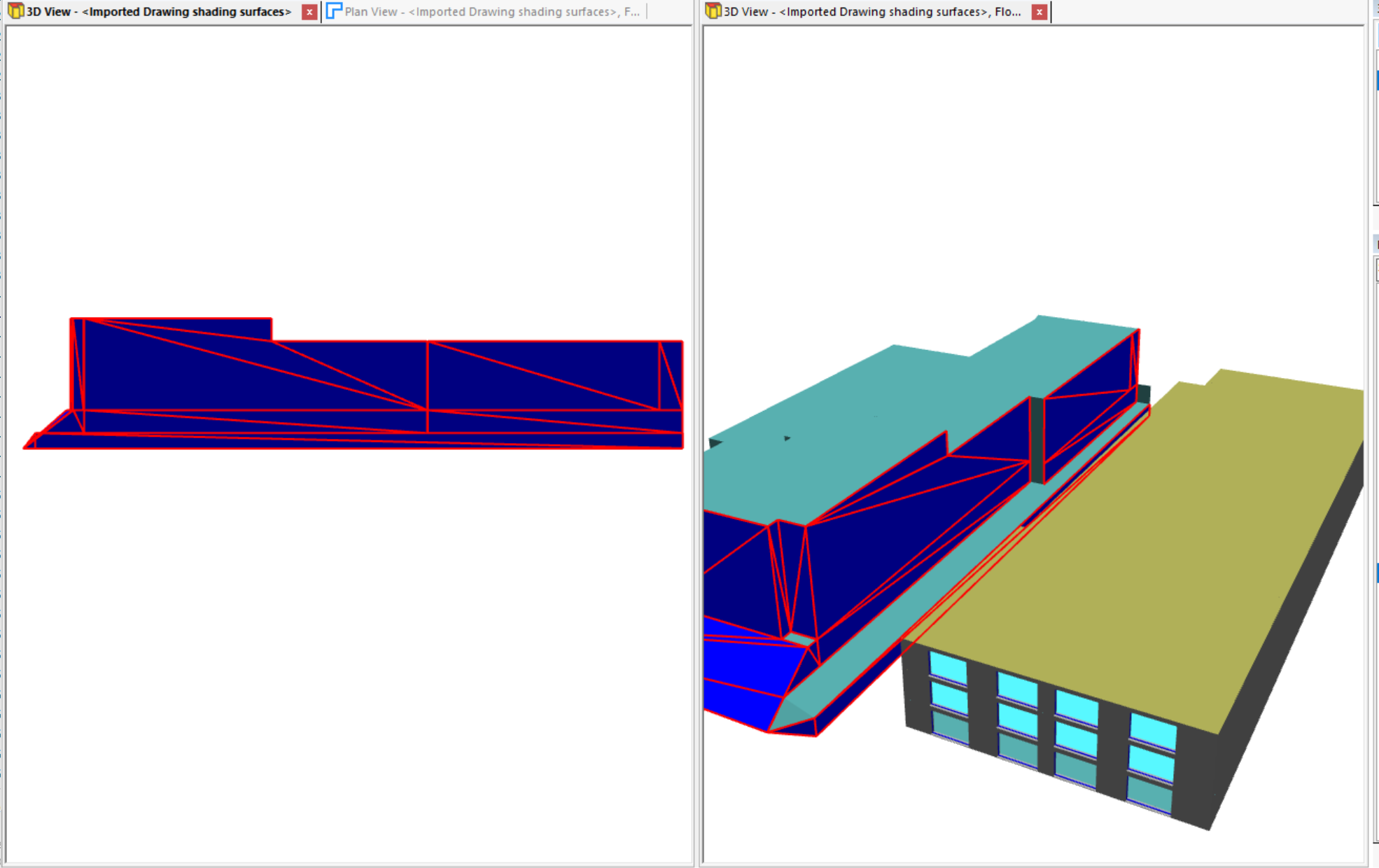
Editing the Shade Surfaces
Upon import, a new storey is added to the model called <Imported Drawing shading surfaces>. This can be selected in the 3D View filter as for other storeys. Note also that new building elements have been created, with the names of the layers in the DWG file and the DWG file appears in the sidebar if not there previously.
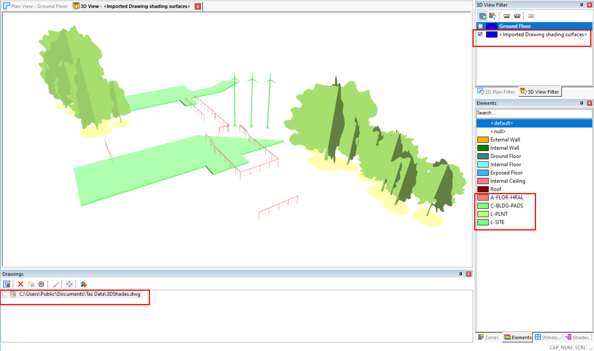
Deleting the storey using the option in Model >> Storeys will remove all the surfaces. Surfaces can be added from another DWG file at any time to the current surfaces, or all the current surfaces can be replaced.
Note
Be careful not to re-import the same surfaces again as this may cause errors in a Daylight Calculation. See below.
Surface Selection
A surface mesh can be selected for limited editing using Model >> Select >> Wall. All imported 3D surfaces are classified as a Wall for this purpose. An individual surface mesh can be selected by clicking on it or use the options in Model >> Select, by Type for example.
Selected surfaces can be deleted. Or a new building element assigned: this may be necessary to assign reflectances for daylight calculations if surfaces from one layer differ.
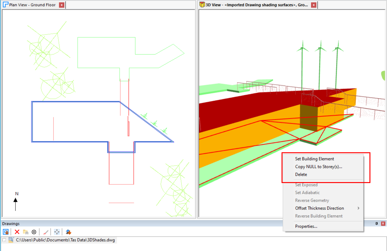
The option Copy NULL to Storey(s)… can be useful for the creation of walls in the Modeller. Select vertical meshes for this operation and then edit the resulting walls as usual in a Plan View, for example, change the Building Element from NULL. The z position of the resulting NULL wall is determined by the storey level and height.
Duplicate or Overlapping Surfaces
When an Analysis Model is created, the 3D surfaces are checked as to whether there are duplicate ot overlapping surfaces. Selecting the Warning highlights all such surfaces.
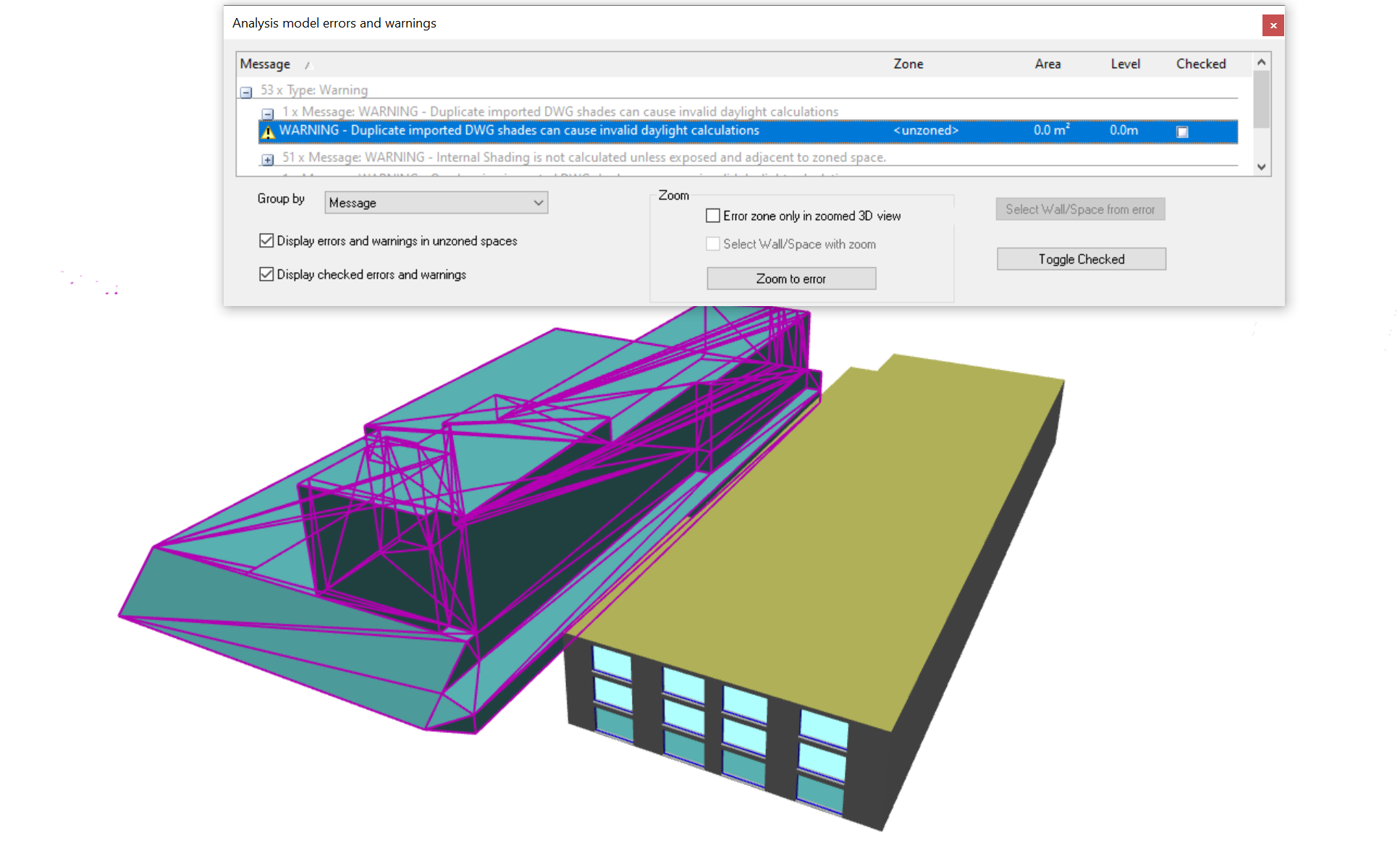
These warnings can be ignored if only shading calculations for the Building Simulator are required, but the surfaces should be checked before any Daylight Calculations. The daylight reflectance convergence can be incorrect if many such surfaces exist.
If this is suspected and it is not possible to fix this by deleting all surfaces and re-importing the required 3D surfaces, the duplicate surfaces should be selected and deleted.
Shades are only included for their reflective effect within a 30m distance of the building model. Therefore the selection process can be limited to this area. An easy way to remove duplicates is to select all the surfaces facing the model and assign a new Building Element to them. The duplicates can be then be selected via a Type Select, using the original layer name and deleted.
Note
To select the shade surfaces facing the building, display them in an Orthographic view such as Front and then use Rectangle Select. This only selects the surfaces that are “seen” ie not the duplicate ones behind.