Planes
This section will demonstrate common uses of planes. For very complex planes, consider using a gbXML import.
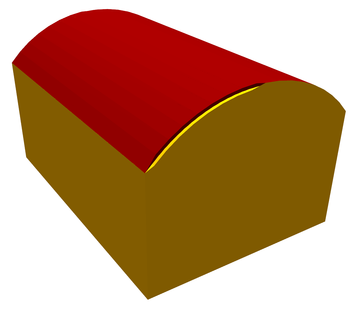
Curved Roofs
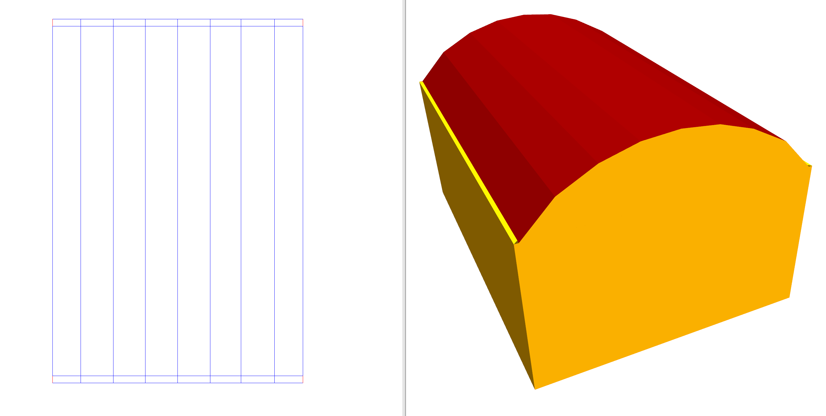
In the first part of this example, we’ll model this curved roof:
We’ll then have a go at modelling a domed roof:
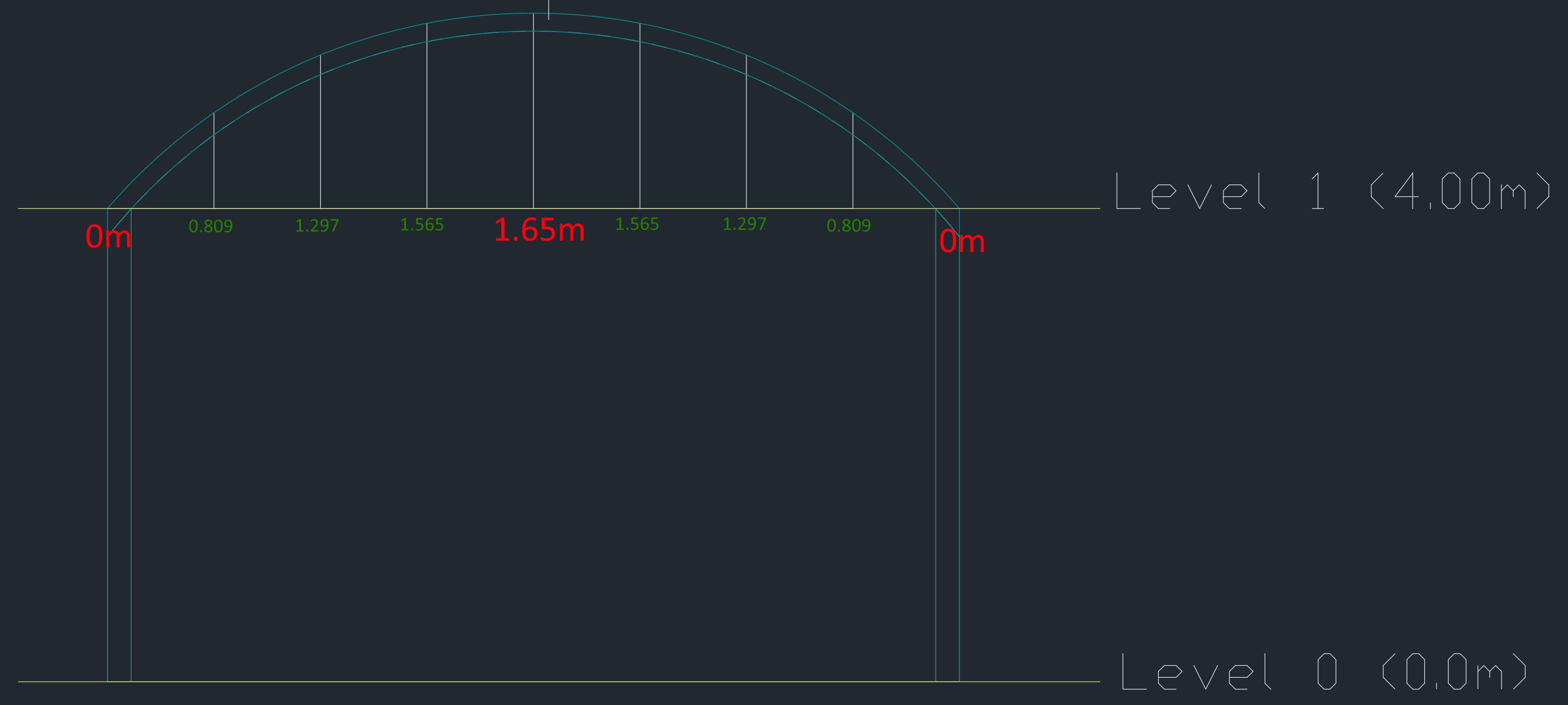
When creating curved roofs in the 3D modeller, it is very useful to have sections to refer to, as these show the heights of the roof at various positions.
Note
In the 3D modeller, we use walls to mark areas of equal height. The 3D modeller then automatically uses these to construct the roof.
Curved roof
Start by creating the two storeys shown in the section:
There should be a storey with level 0m and default wall height 4m, and another storey with level 4m. The default wall height of the second storey is of little significance.
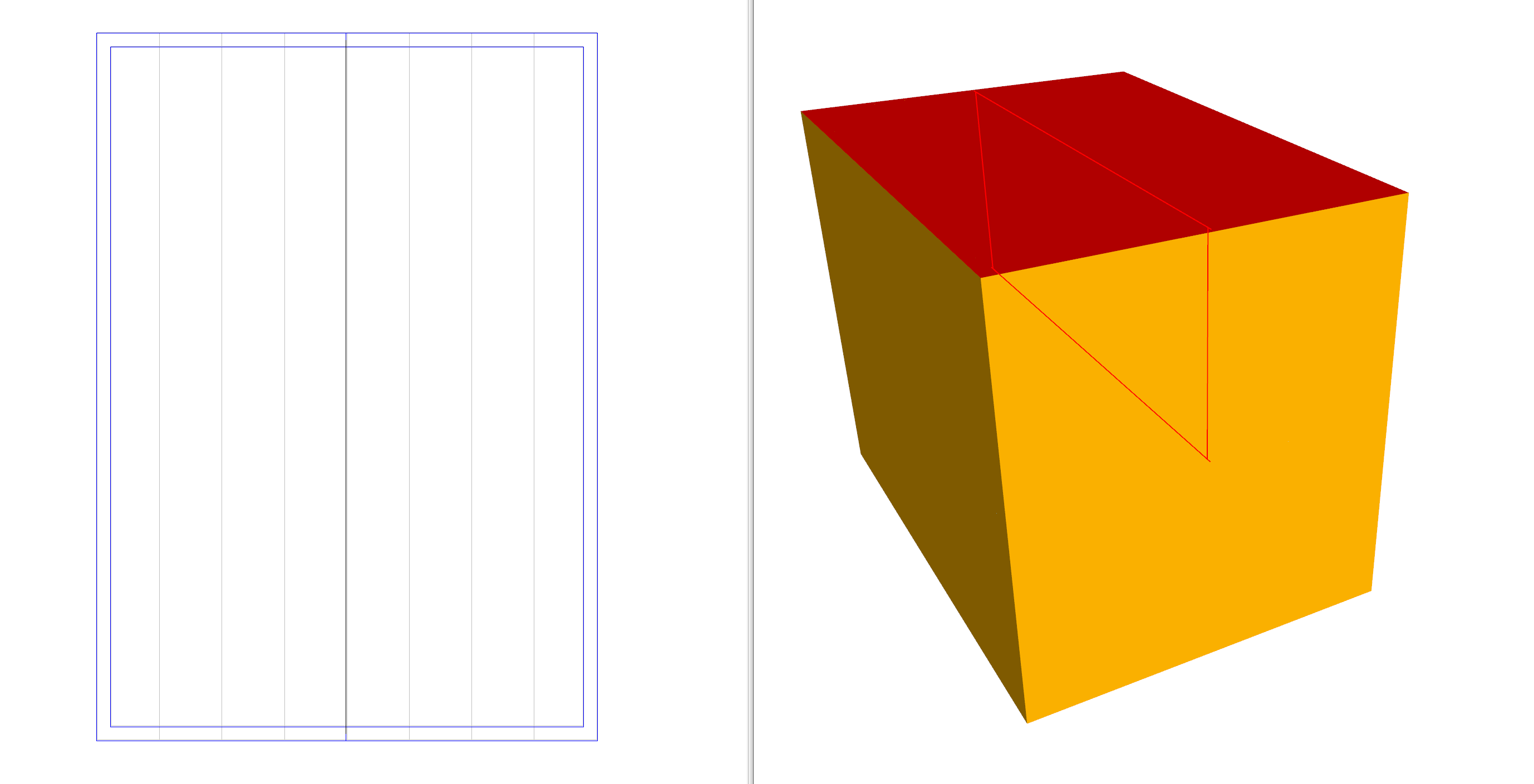
Then, draw in the walls on both storeys:
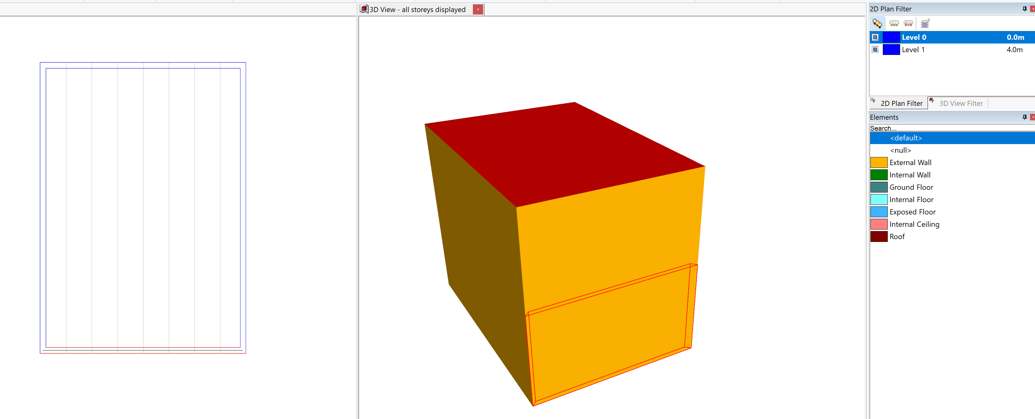
We can see, in the 3D view, we now have a flat roof instead of the curve we desire.
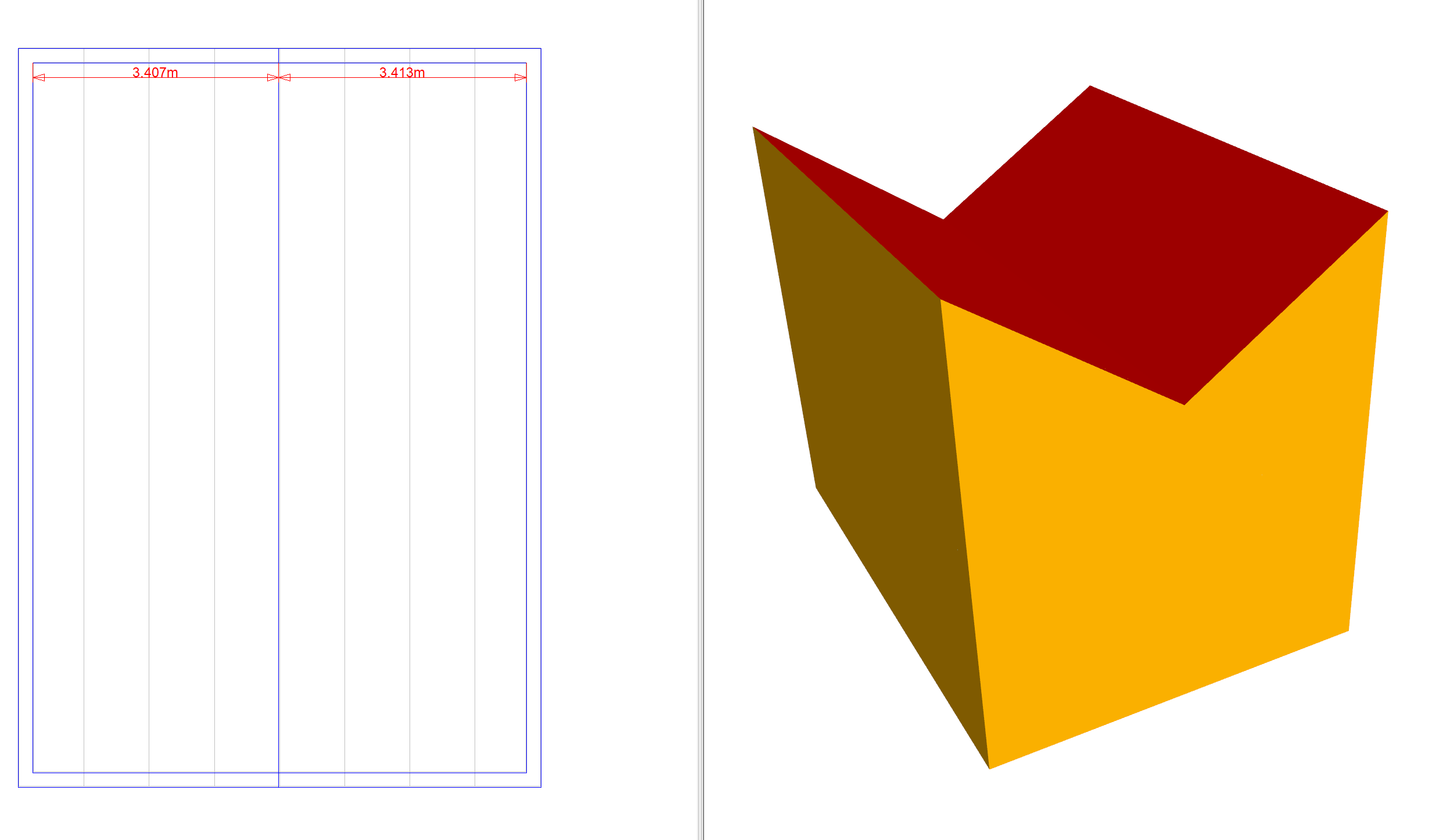
Draw in a null wall where the highest point on the roof is:
Set the height of this wall to be 1.65m, as shown in the section. Remember, the wall height is relative to the currently selected storey:
The height of the outer walls should now be set to 0m:
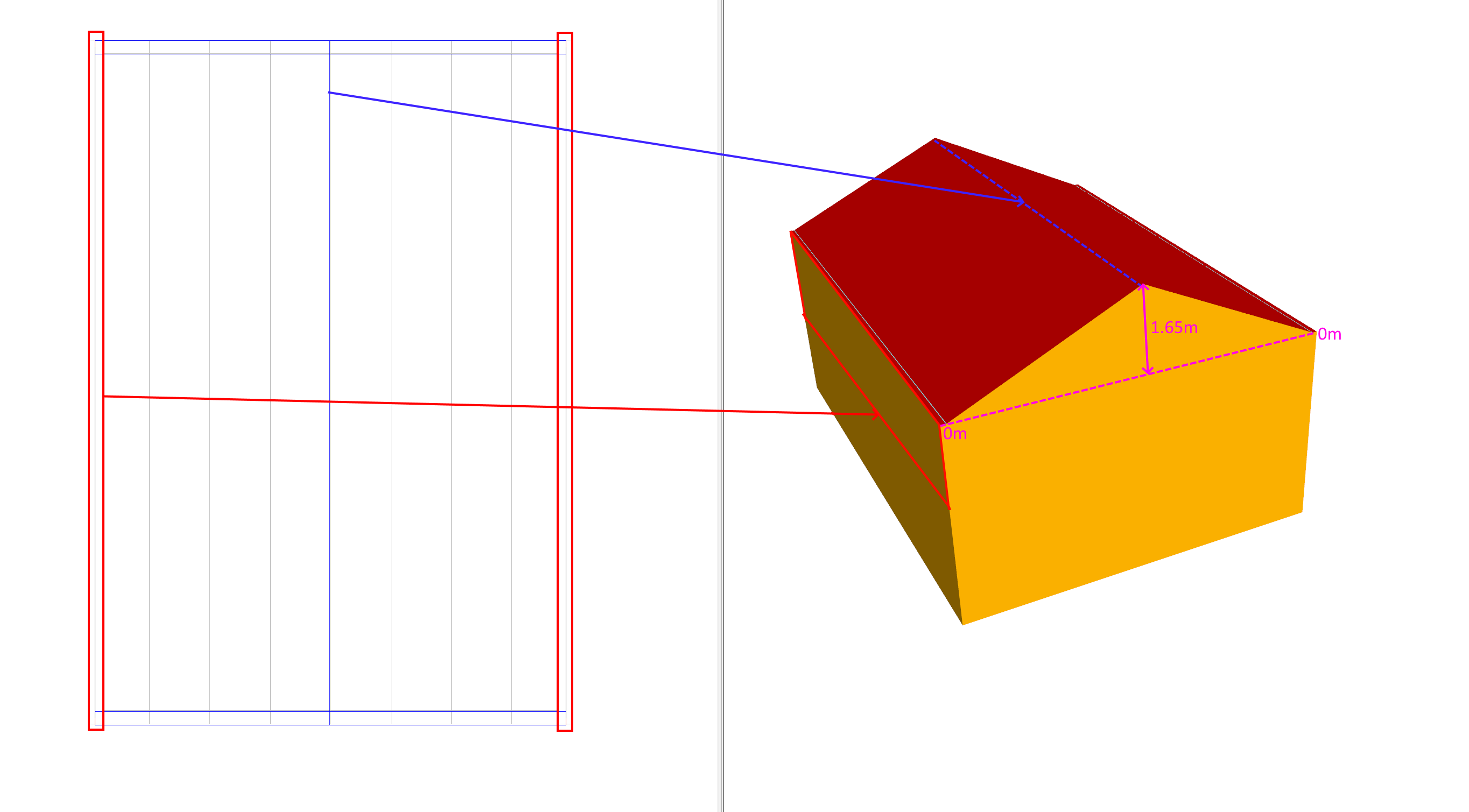
We now have a very poor approximation of our curved roof. To make the approximation better, we can add more null walls and set their heights:
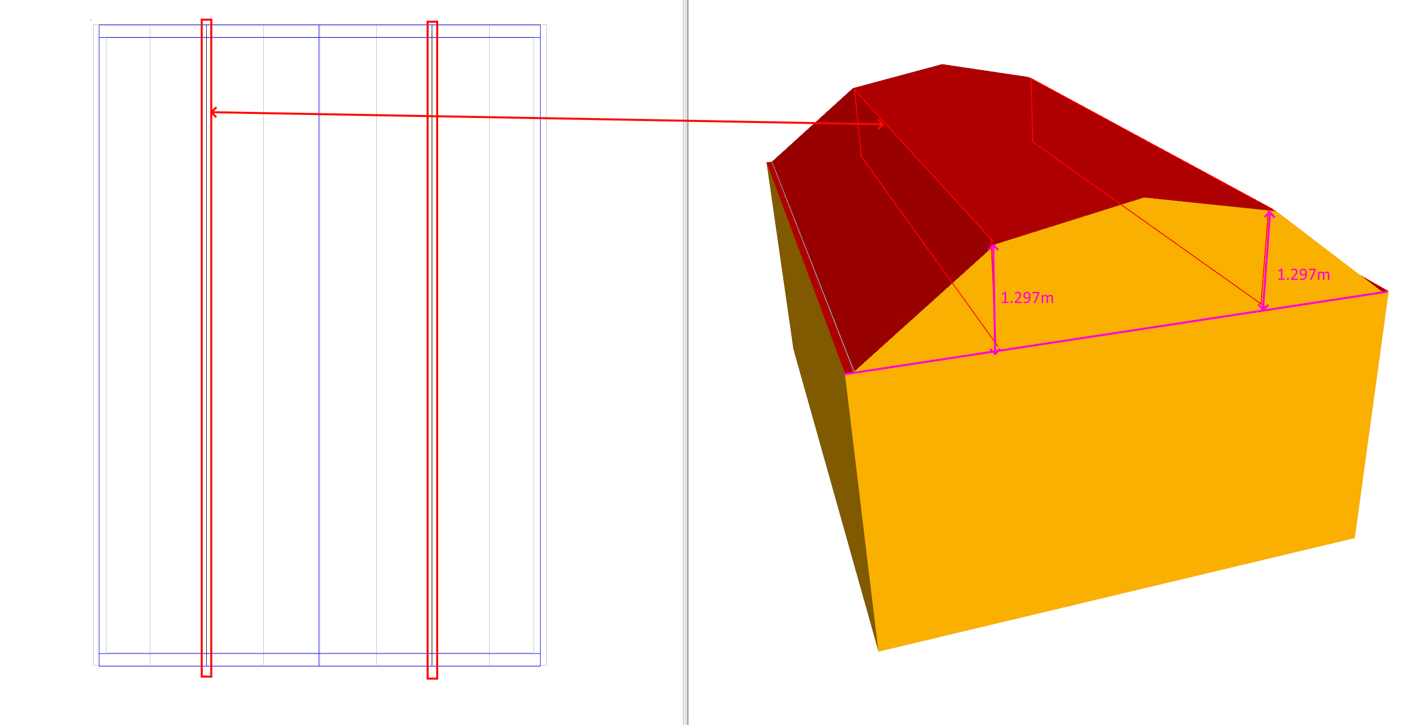
Here, an additional two walls have been added at 1.297m as measured from the section.
The more null walls we add, the smoother the curve will be:
Note
When creating compelx roofs using multiple null walls, drawing the roof on its own storey will make creating internal partitions and zoning easier.
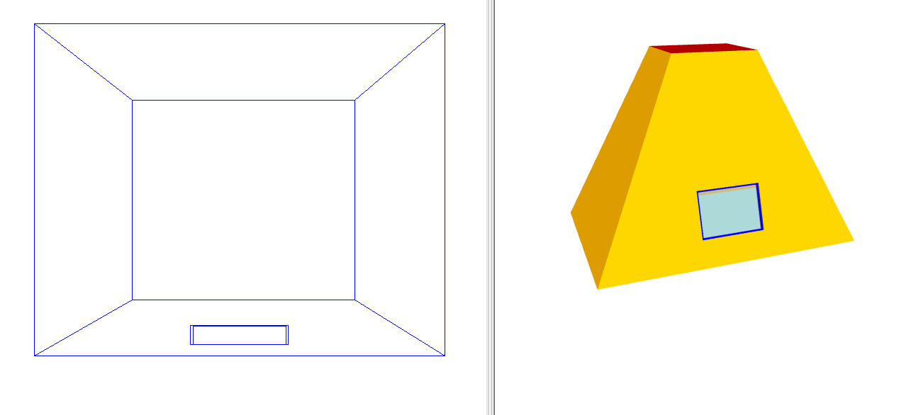
Domed Roof
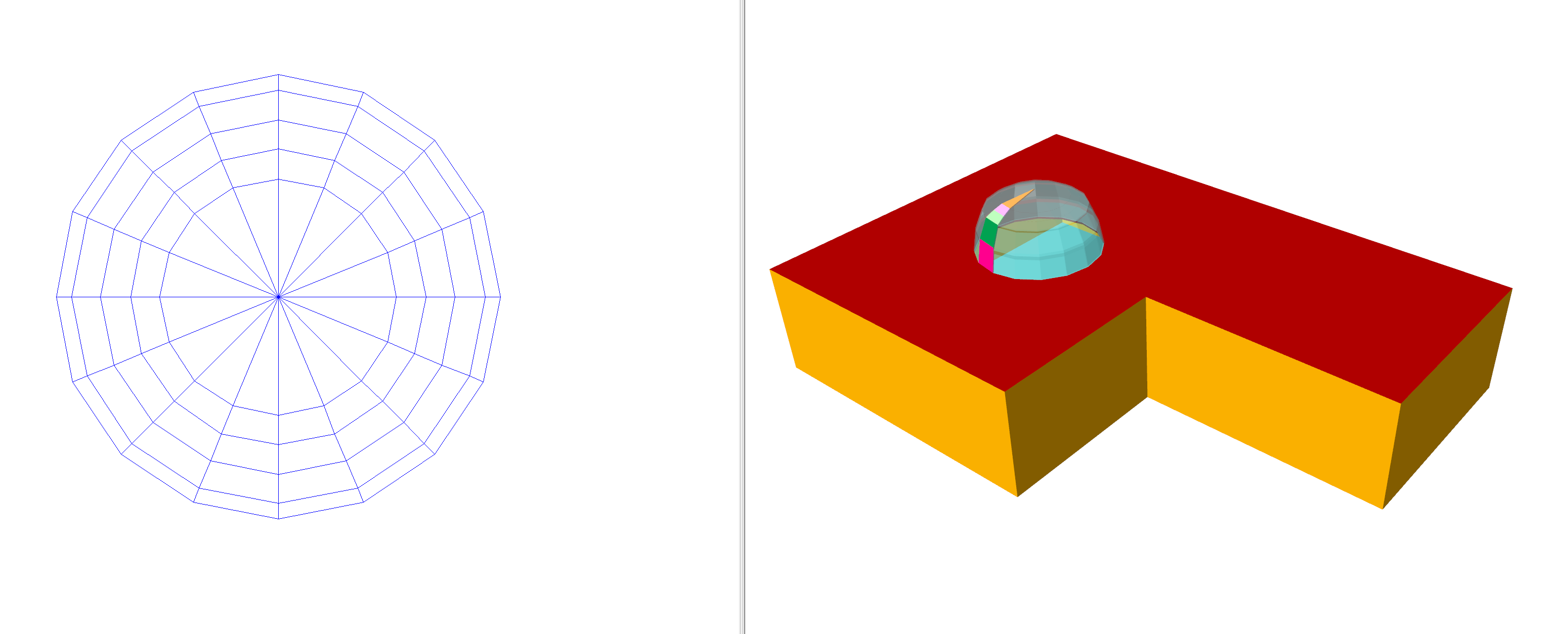
Creating a domed roof is very similar to creating a curved roof. The key is to identify the contours of equal height:
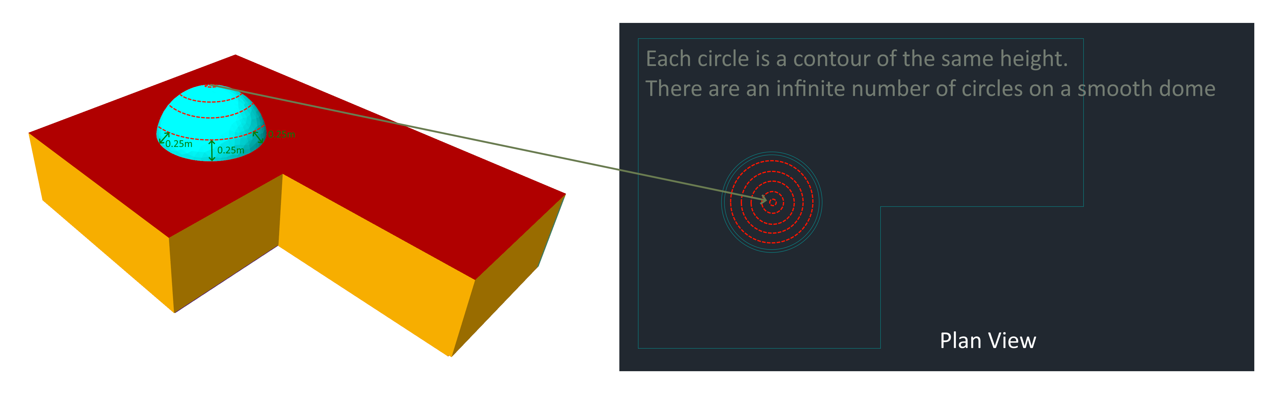
In this example, we will model the above building which has a glass dome as part of its roof.
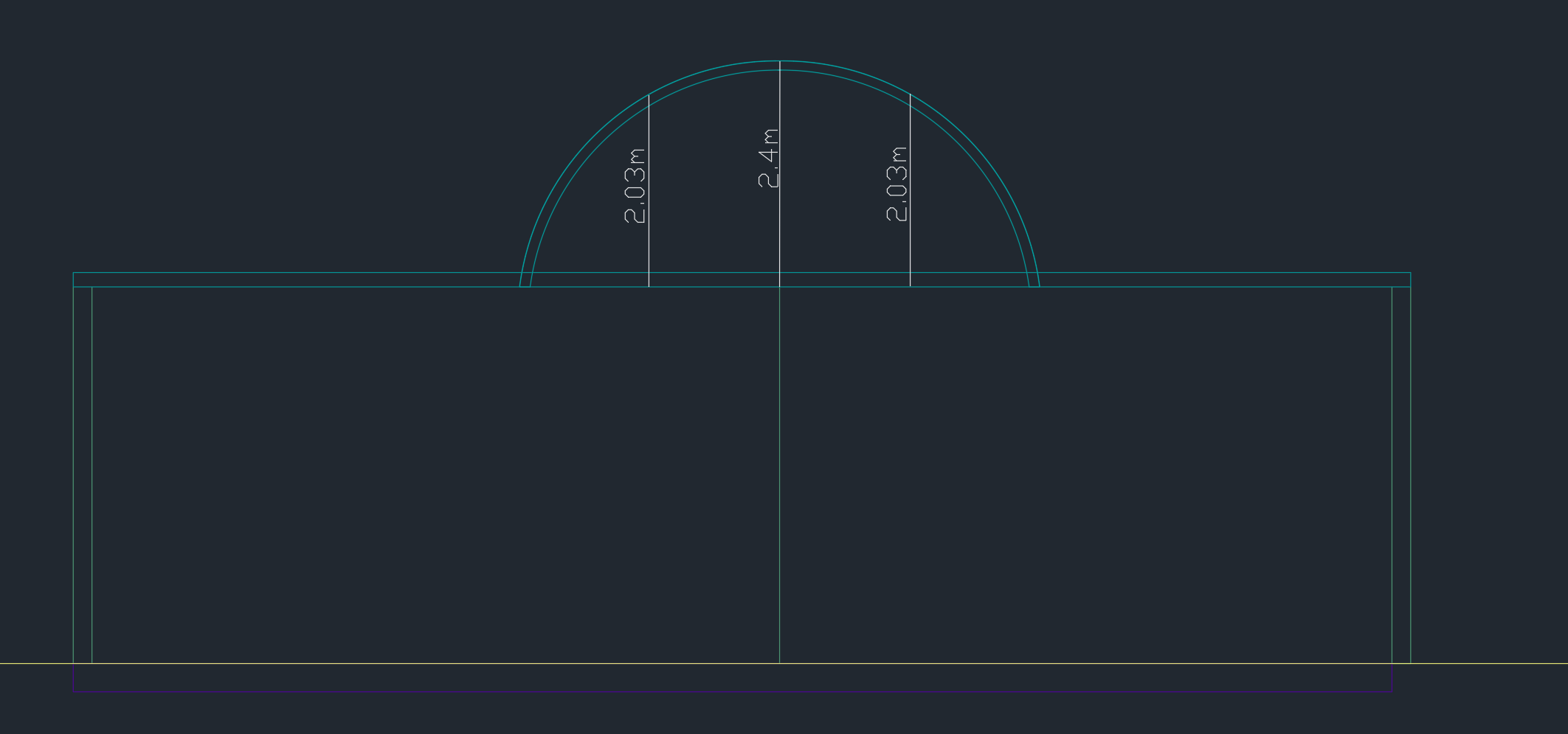
The section through the centre of the dome is as follows:
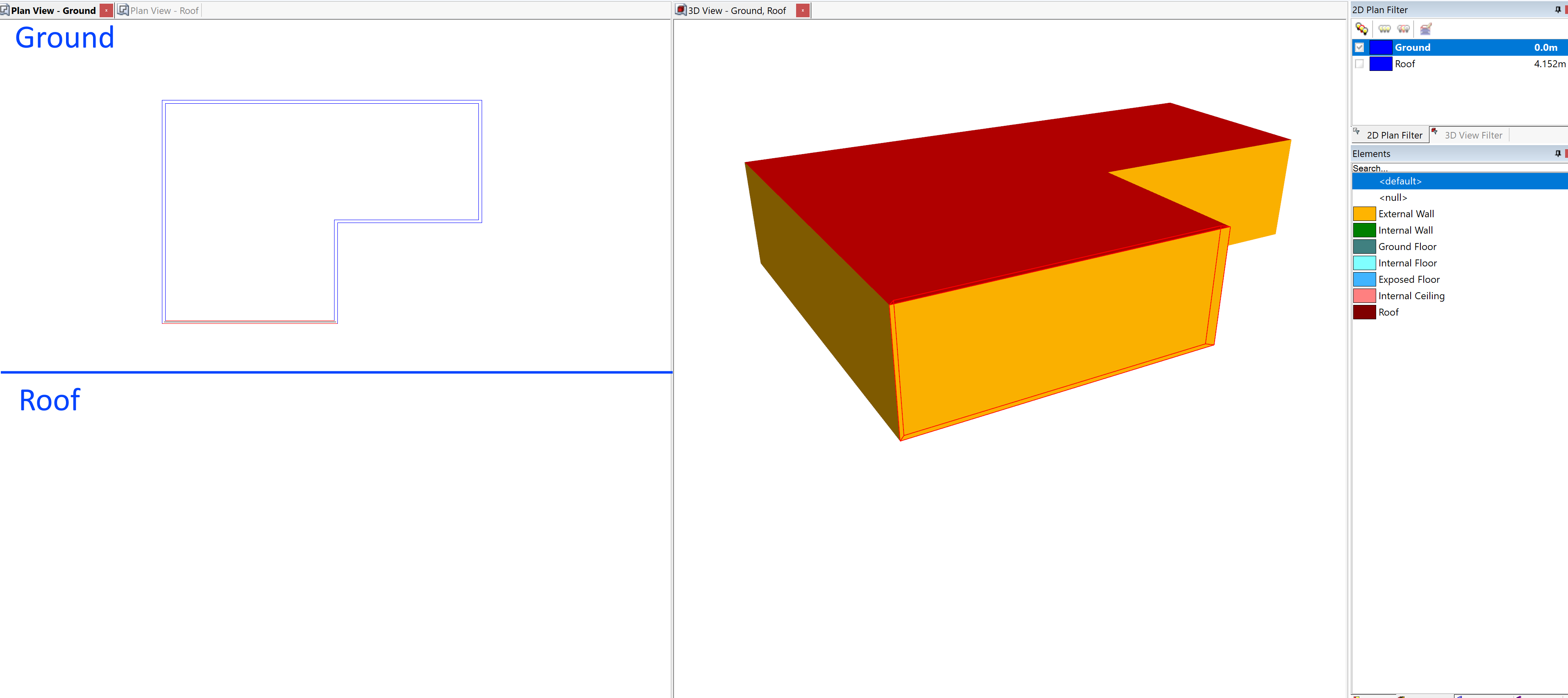
In the above, the height of the ground storey is 4.15m. As before, start by creating the storeys. Then, add the walls for the ground storey:
We will draw the dome using 16 smaller walls. Set the grid angle to 11.25° to make this easier. The radius of our dome is 2.3m, so place 16 null spokes which are 2.3m in length:
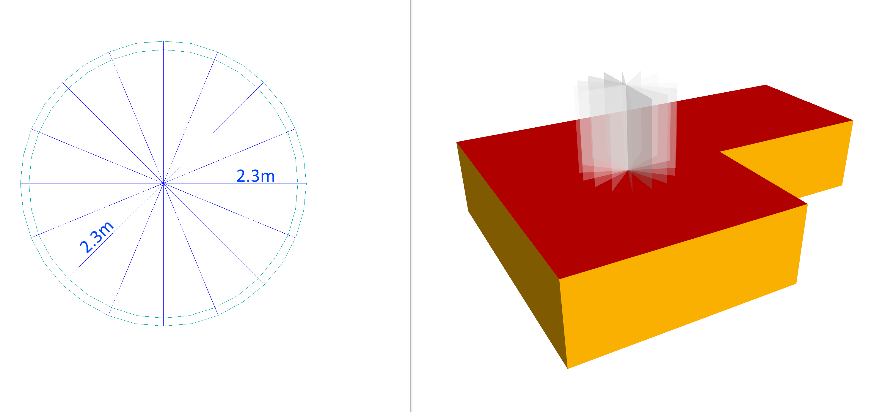
Now draw in the outer edges of the dome:
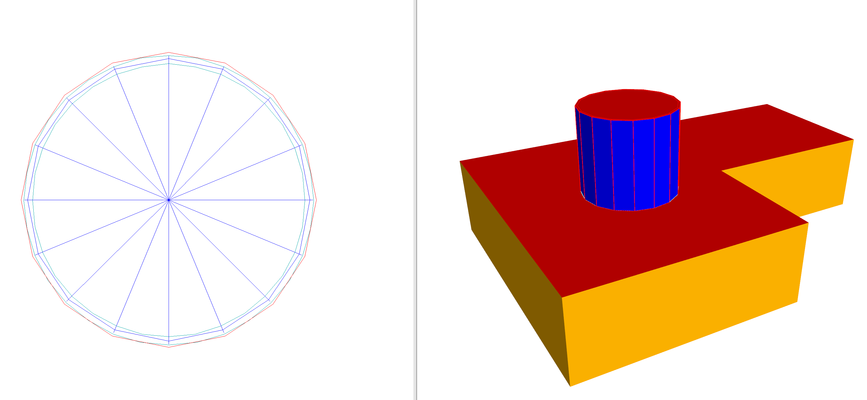
We can now set the wall height of the edges to be 0m, and the centre point height to be 2.4m as read from the section:
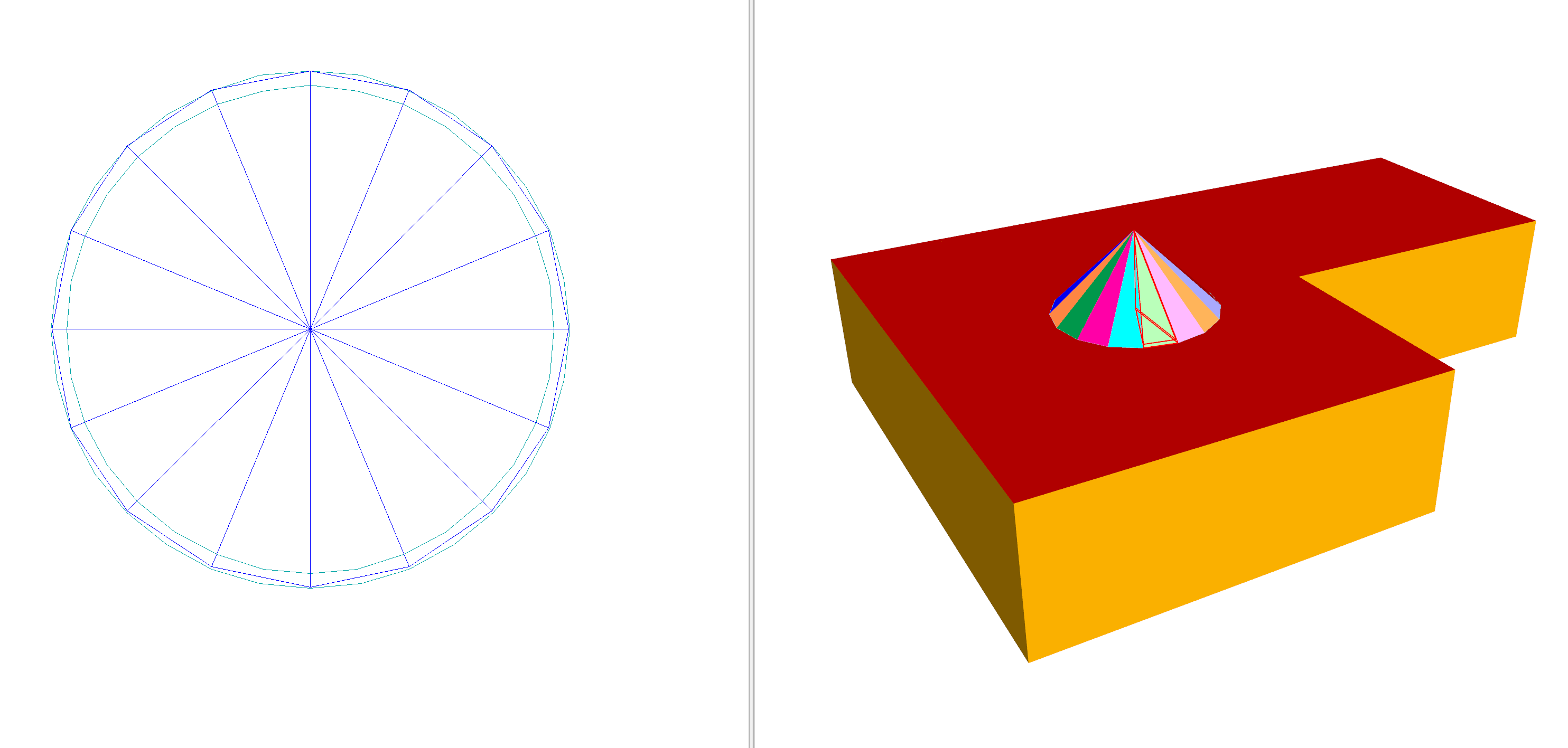
We now have a cone, which is a poor approximation of the dome. To make the approximation better, we can add more null contours. With two:
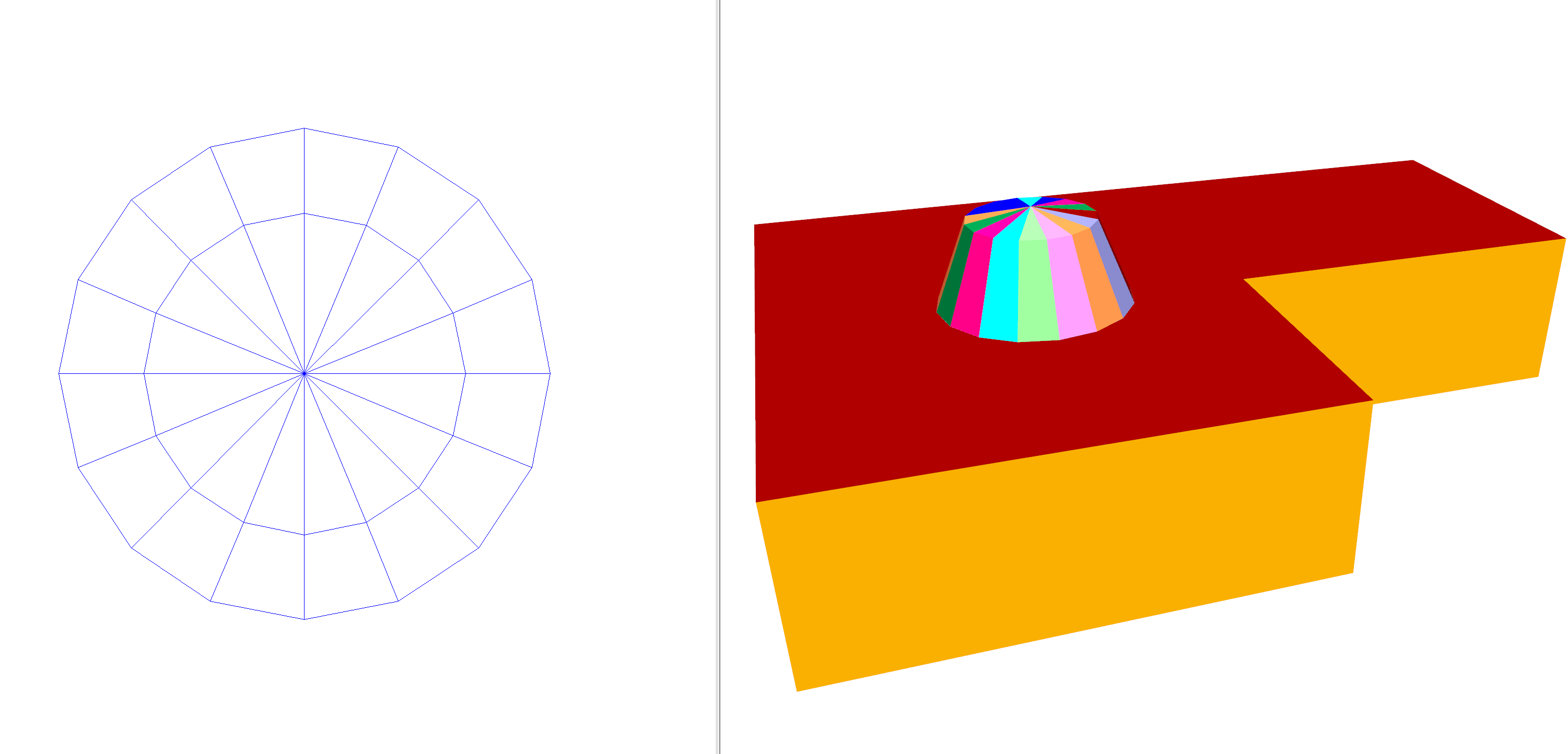
And with 5 contours:
Note
Spacing contours closer together where the height changes rapidly will result in a better approximation.
The floor element of the dome was set to null and the perimeter was copied to the ground storey. The outline on the ground storey had its ceiling element set to null.
Dormer Windows
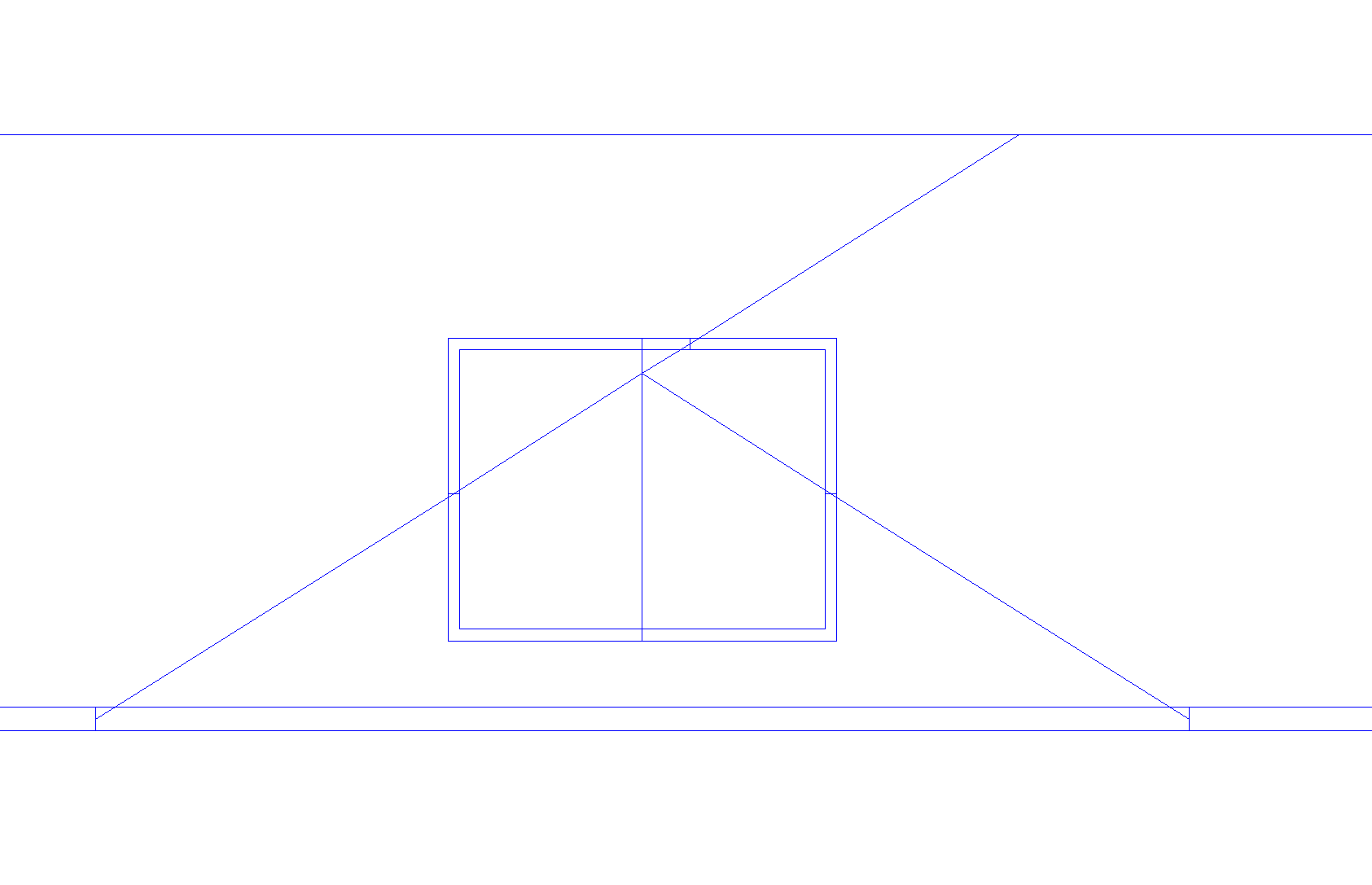
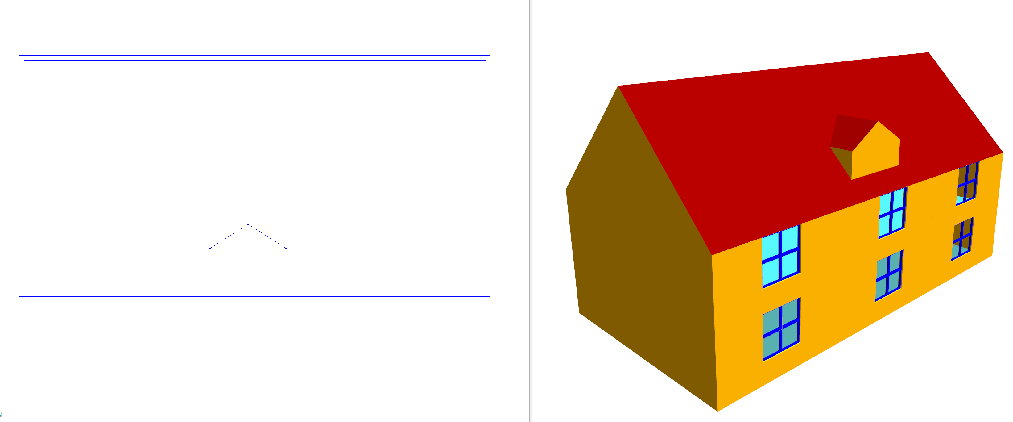
Drawing dormer windows in the 3D modeller involves creating planes for each of the sloped surfaces, and then using the intersect planes tool to determine where they cross:
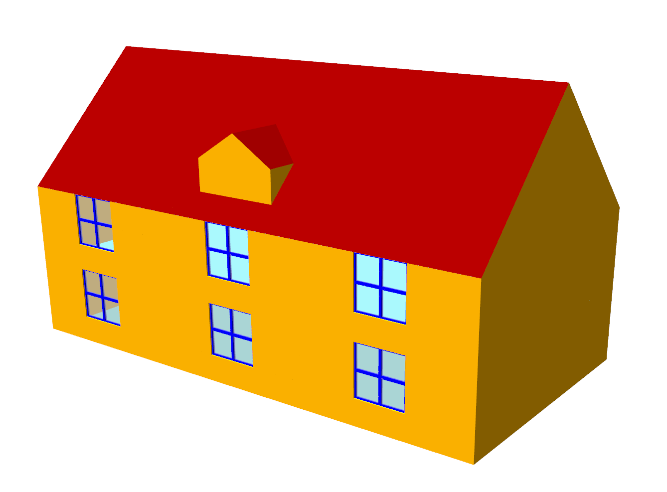
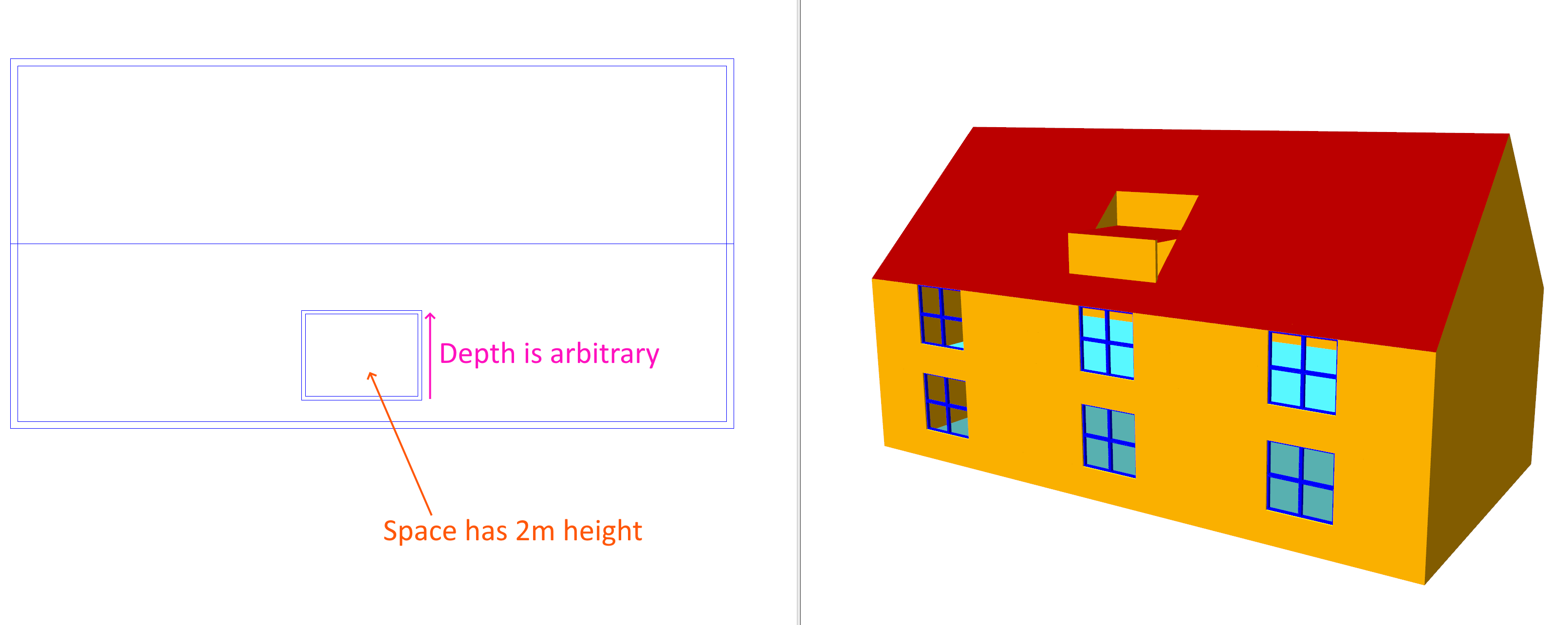
To model the above, our starting point is the building without the dormer window:
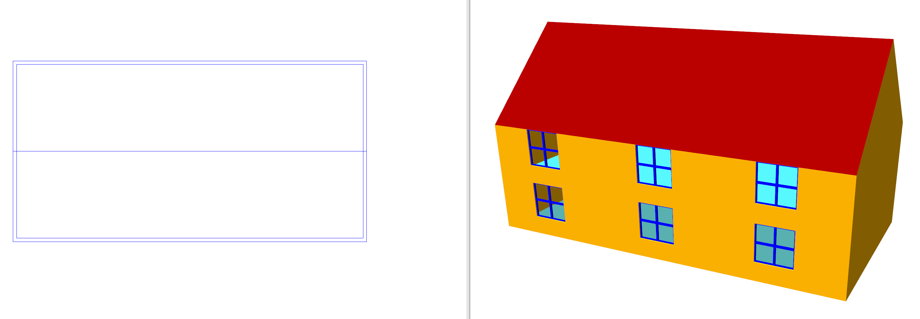
The nearside of the roof has a sloped ceiling using a plane called Front Slope:
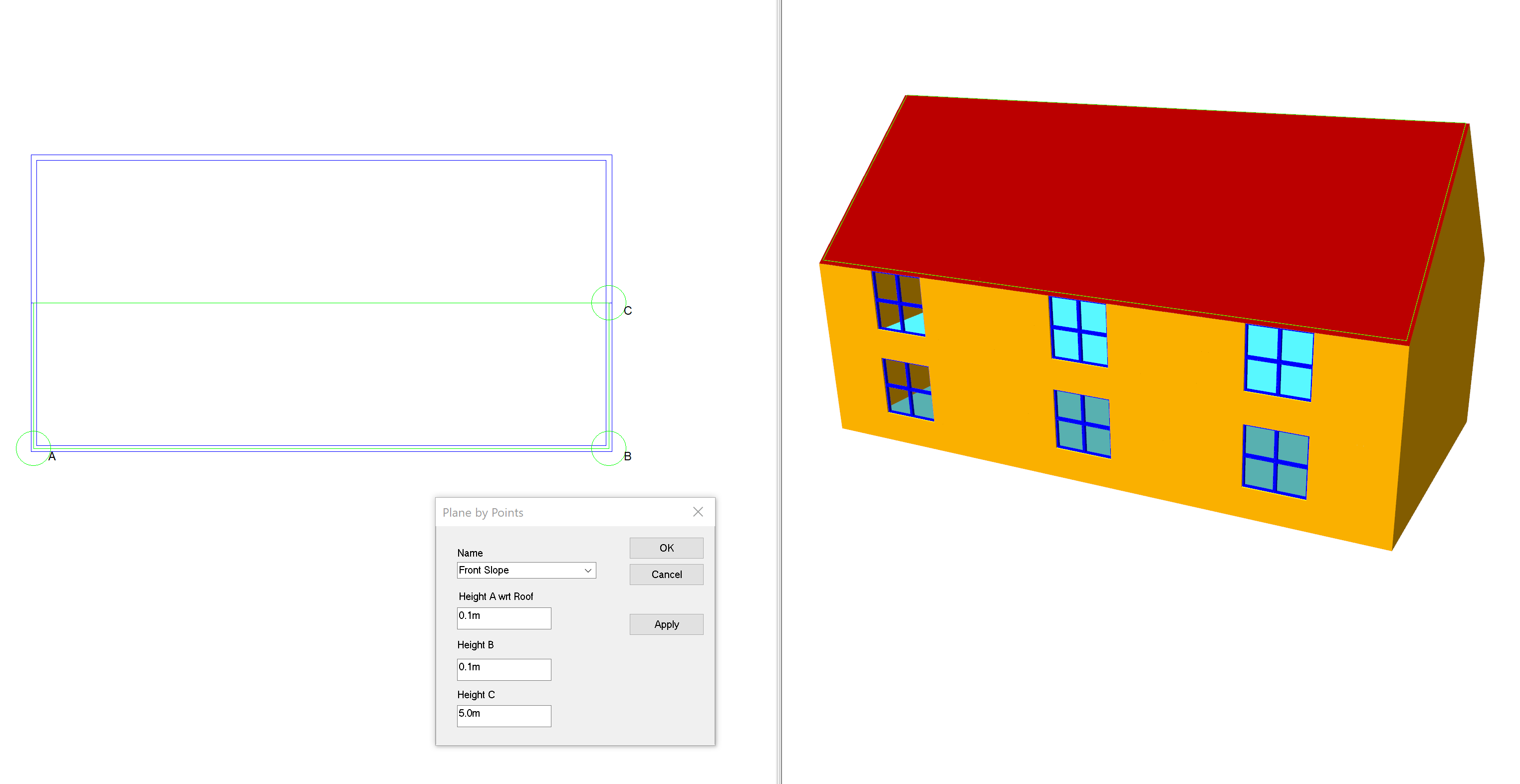
Now place walls where the dormer window will be. The depth of the dormer window does not matter as it will be trimmed later:
Note
If the roof slope disappears at any time, just re-apply it!
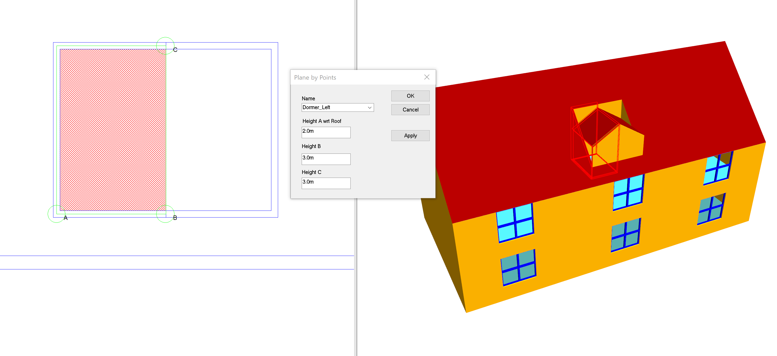
The dormer window we are modelling is a gable window, so create two planes for each side and apply them. The lowest point has a height of 2m, and the middle has a height of 3m:
If you look closely, you will see that we need to extend the main part of the roof until it intersects with the dormer window:
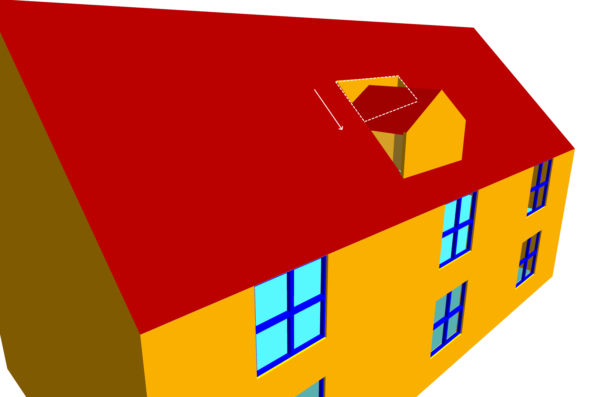
In order to extend the main roof appropriately, we need to know where the plane of the main roof intersects with the planes that form the dormer gable.
We can find this by using the intersect planes tool:
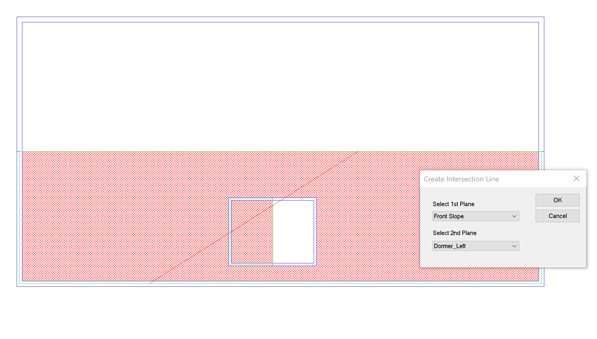
Repeat the process by intersecting Front Slope with Dormer Right:
Now trim away the extra bits of wall we no longer require:
At this point the dormer window should be complete. If some of the ceiling slopes appear to be broken, just re-apply them.
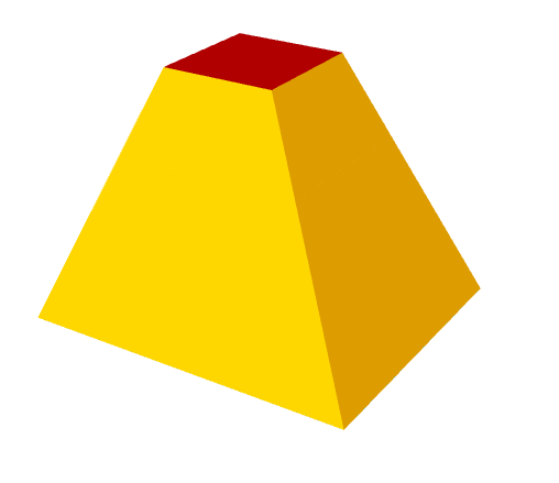
Sloped Walls
In this example we will create the following small model which has two storeys and has sloped walls:
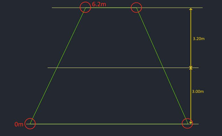
In order to facilitate the modelling process, it is useful to have sections, elevations and floor plans clearly showing the heights of the walls, ceilings and floors:
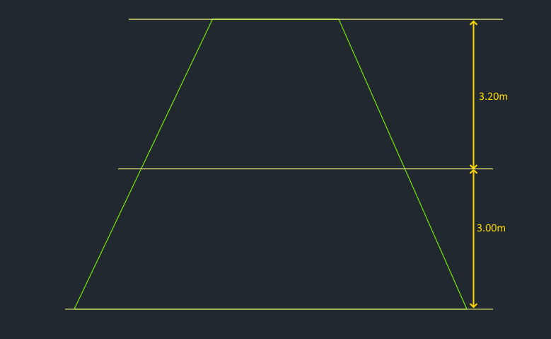
First, create the two storeys as shown in the above section.
Import the two floor plans and go to the lowest storey. Place the perimeter walls for the lowest storey:
Now, still on the lowest storey, place in the walls where the sloped wall will cross the boundary between the two storeys. This will be the same as the perimeter wall of the next highest storey:
Place the diagonal walls for each of the sides:
Now repeat the process for the next highest storey:
As explained in Planes, sloped walls are modelled by sloping ceilings & floors so they are indistinguishable from walls.
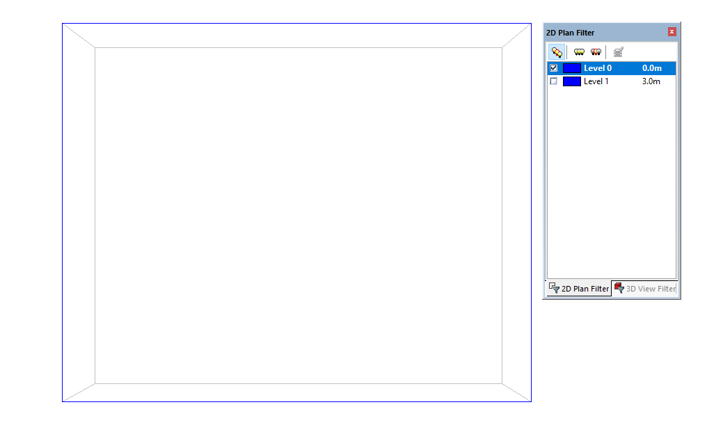
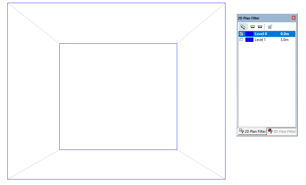
To model sloped walls that span several storeys, it is useful to define the plane at its lowest and highest point as this produces accurate slopes. In this example, the highest and lowest points are here:
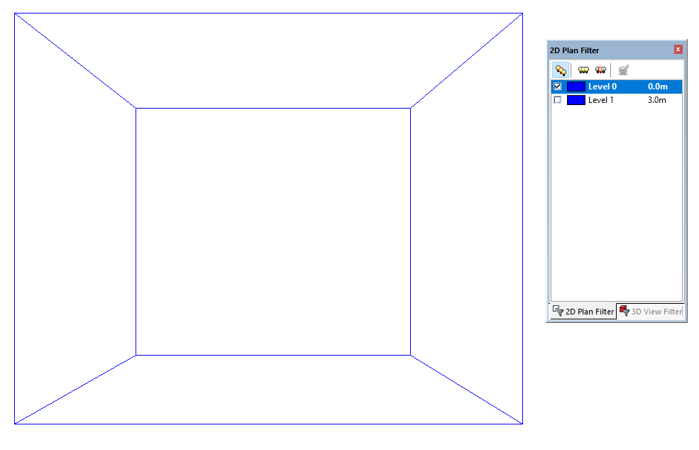
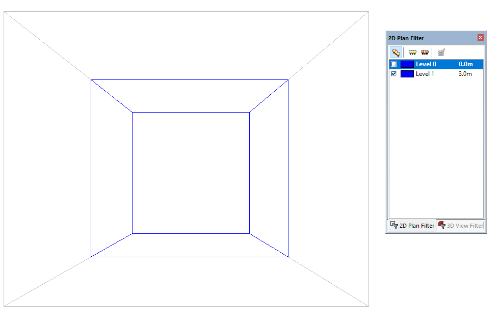
We use the select joins tool together with the create planes by points option to define the planes that span several storeys. To select joins on multiple storeys, adjust the 2D plan filter to include multiple storeys:
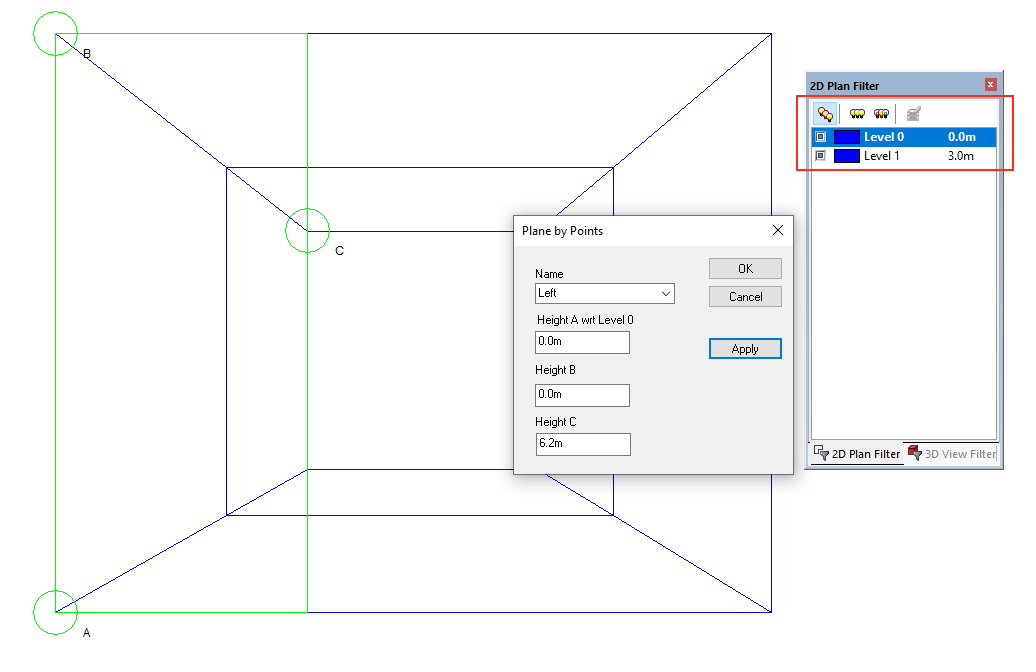
Create the 4 planes, one for each sloped wall. The planes can now be applied to the ceilings of each space that makes up a wall:
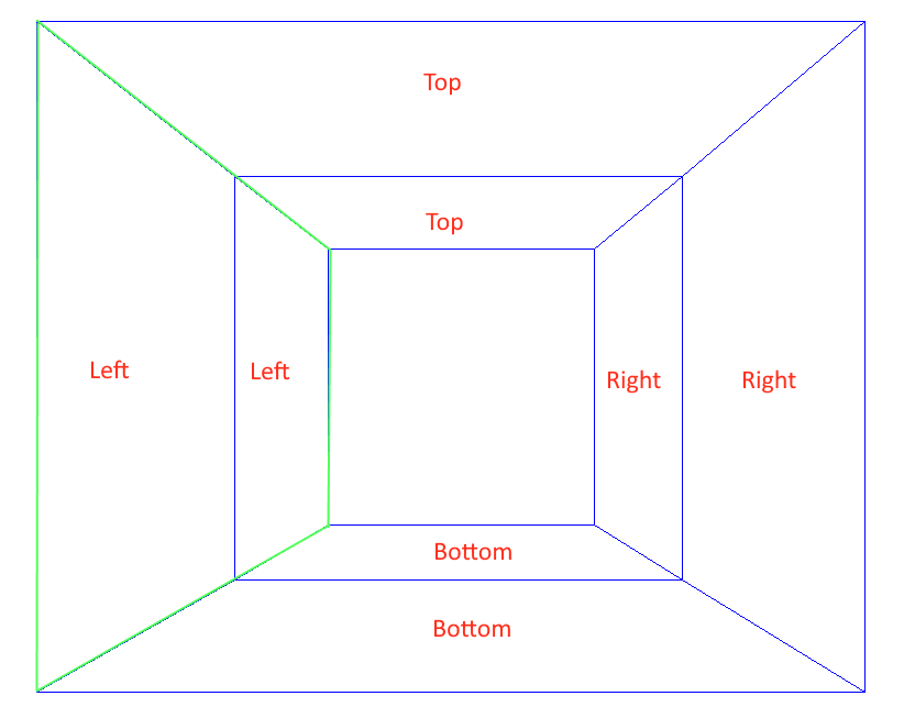
The spaces that make up the walls can now be assigned an External Wall building element:
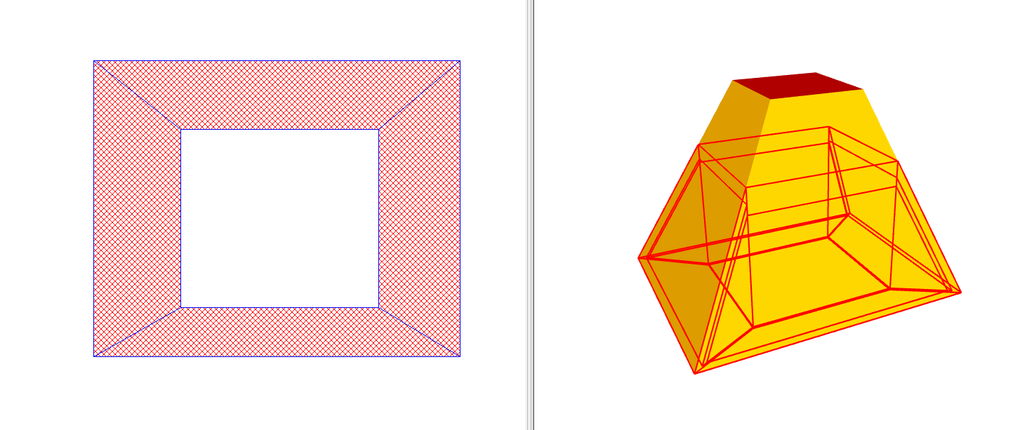
Don’t forget to check the include sloping floor area checkbox for that building element.
Windows can be added to the sloped walls using the rooflight placement in the create windows dialog: