Windows
In the 3D modeller, Windows are used to model:
Windows
Louvres
Rooflights
By default, windows also have an associated frame.
Placing a window in the 3D modeller results in surfaces in the Building Simulator with automatically created Building Elements for the pane and frame of the window:
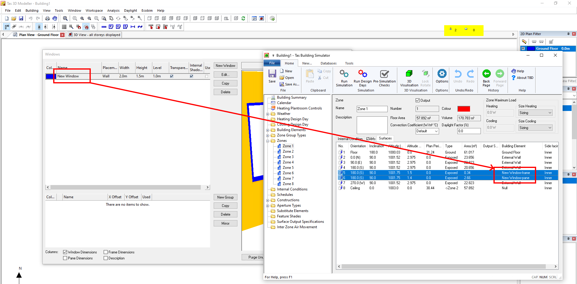
Note
Each Window in the Windows create/edit dialog will have a pane and frame Building Element associated with it in the Building Simulator.
If you need to apply a different construction or aperture to an instance of the same window, you should copy that window in the 3D modeller.
Creating Windows
To add new Windows to the 3D model, click model >> create/edit >> Windows in the ribbon:
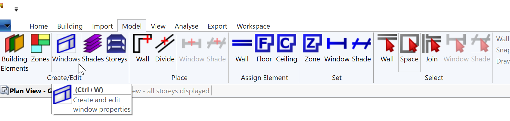
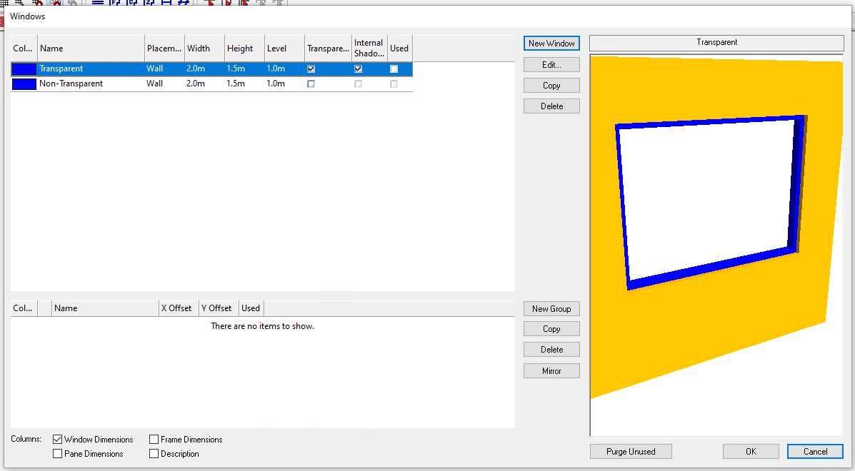
The following dialog will open:
Placement
The placement of a Window can be one of:
Wall
Roof
Floor
Door
Full Wall Height
The placement determines where the window can be placed in the 2D plan view. Wall, Full Wall Height and Door can only be placed in walls.
Roof and Floor windows can only be placed inside a space, as they will become part of the floor or ceiling element of that space.
The Roof and Floor options are used for modelling rooflights and windows between floors.
The Door option creates a window that will automatically have a level of just above the building element thickness of the floor of the space it is placed adjacent to:
If you didnt use the Door placement, you would need to use two different Windows to achieve the above effect.
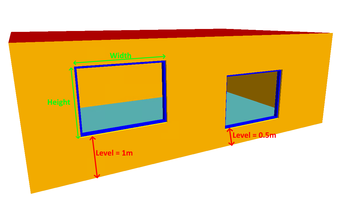
Window Dimensions
The window dimensions are entered via the Width and Height property in the dialog, and include the frame if the frame is present.
Level
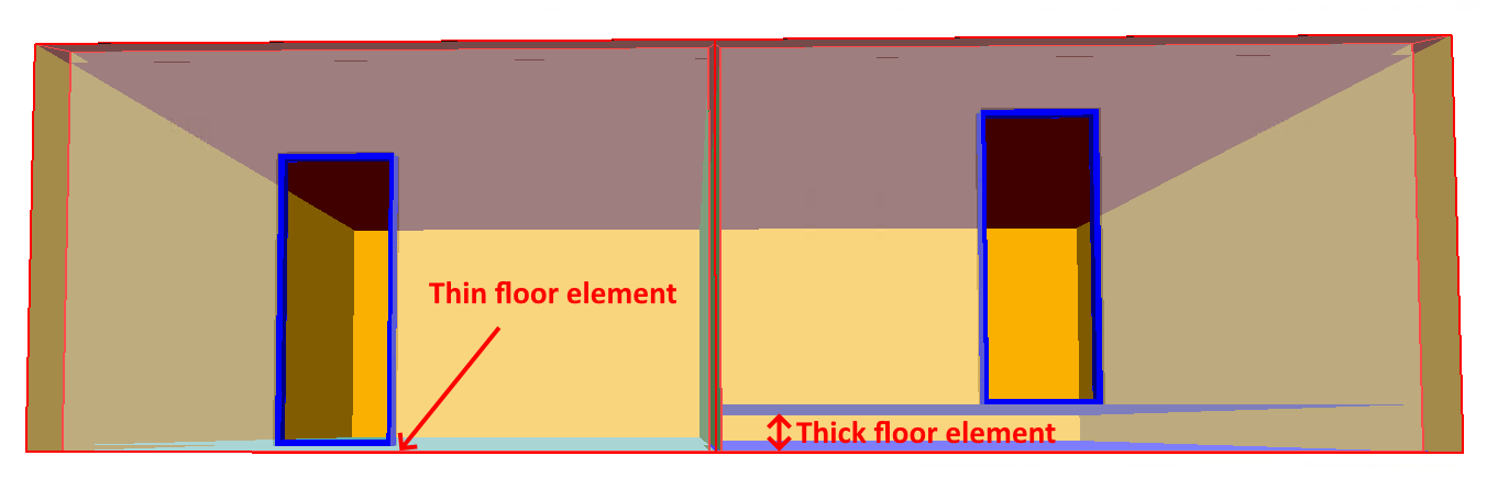
The level of the window is the height above the current storey at which the window is placed in the wall:
As the level is measured relative to the start of a Storey, is not above the thickness of Building Element assigned to the floor.
Transparent
The transparent option is used for modelling transparent surfaces; if it is not checked, the Window will still have a frame and pane in the Building Simulator, but will not allow light to penetrate in the 3D model:
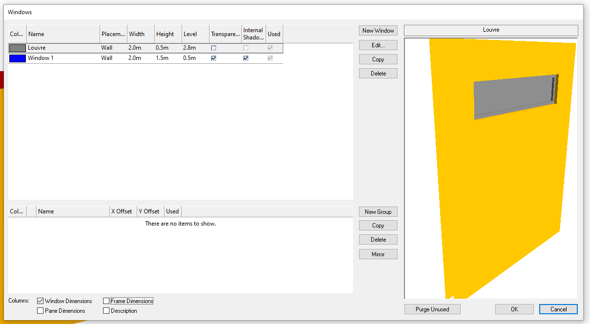
This is often used to model louvres or spandrel.
Transparent elements in the 3D modeller, including windows, affect Daylight and Shadow calculations in the 3D modeller. They do not affect the thermal simulation in the Building Simulator directly.
In the Builidng Simulator, you can assign opaque or transparent constructions elements that are transparent in the 3D modeller, but doing so can lead to confusion and can affect the shading calculations.
Internal Shadows
See Internal shadows for details.
Used
The used checkbox helps you easily identify windows which have not been placed in a model, so can safely be deleted.
Frame Dimensions
You can change the size of a windows frame by checking the Frame Dimensions checkbox:
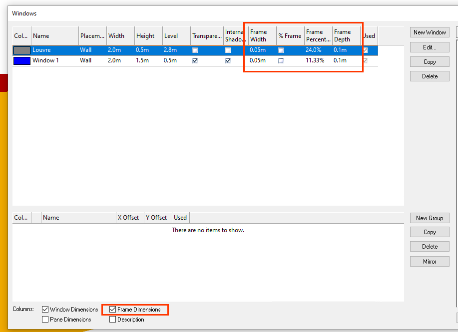
You will then be able to change the Frame Width, Frame Percentage and Frame Depth.
The % Frame checkbox determines whether the width of the frame is given as a percentage (via the Frame Width field), or as an absolute size (via the Frame Width field).
If you do not wish to include a frame for a window, you can set the width to 0%.
Frames are assumed to be non-transparent.
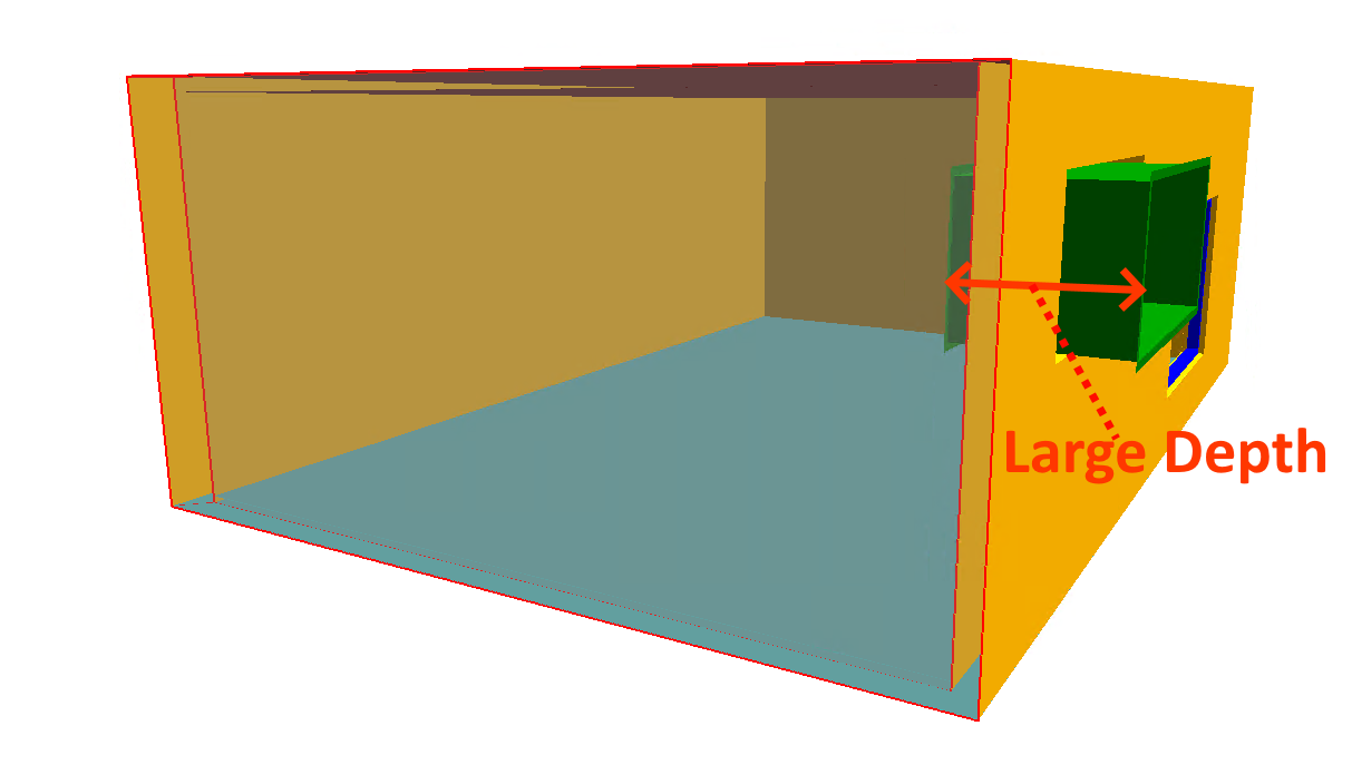
The Frame Depth field is used to alter the dimension of the frame perpendicular to the window:
Pane Dimensions
You can alter the Pane Depth and Pane Offset of a window by checking the Pane Dimensions checkbox:
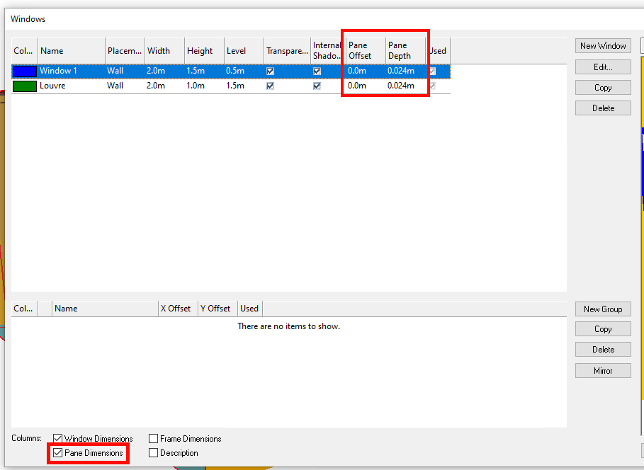
The Pane Offset determines where the pane is placed within the wall, and is useful when modelling recessed panes, or panes that protrude:

The value can be positive or negative.
The Pane Depth field is used to give ‘thickness’ to the pane; this is particularly useful when modelling non-transparent elements, as the thickness of transparent materials is not modelled in the Building Simulator.
The Pane Depth will have a minimal effect on daylight calculations, as the Radiosity based method used in the software does not require modelling refraction between the inner and outer surfaces of the pane.
Window Groups
Window groups are used to combine several windows into a group that can be placed as one in the 3D model.
They are also used when you need to model a window being above or below another window.
Window groups can contain any number of windows or window groups.
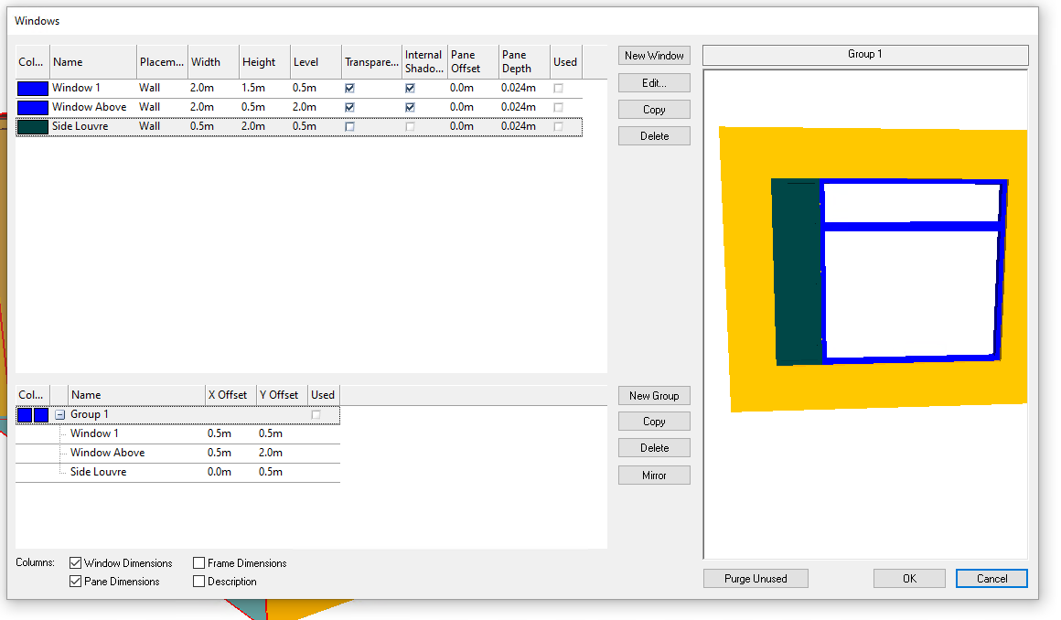
Creating a window group
To create a new window group, click on the New Group button.
You can add windows to this group by dragging them from the top section of the dialog. The same window can be added multiple times:
Note
When you add a window to a window group, the level of the window will be used as the initial y-offset value. This will not change if you alter the level of the original window.
x-offset & y-offset
The x-offset of an entry in a window group is the relative horizontal position of the window within a group.
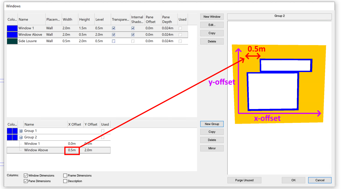
The y-offset is the vertical position of window within the group.
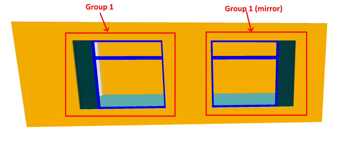
Mirror
The mirror button allows you to create a new window group that is a mirror image of the selected window group:
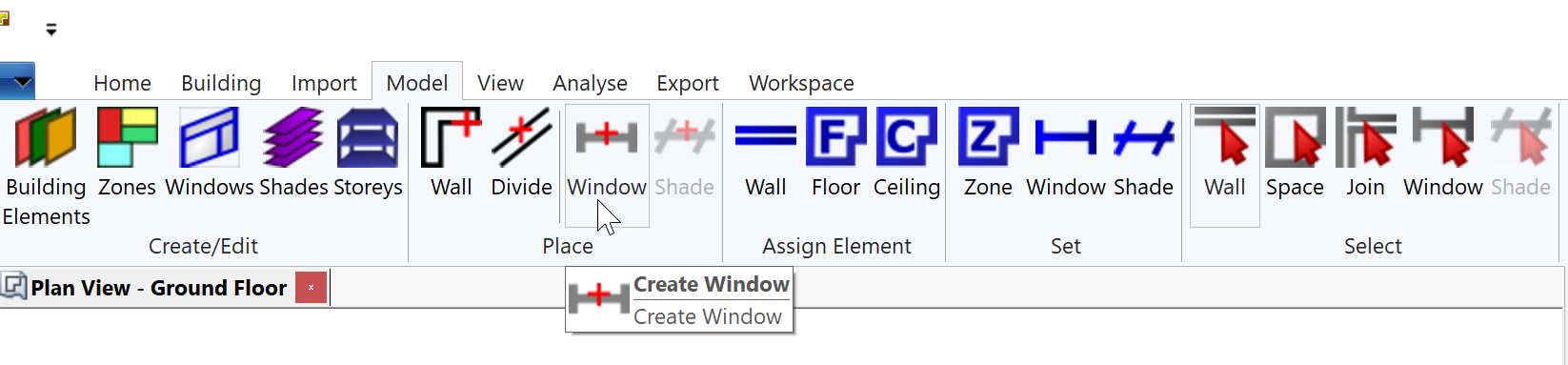
Placing Windows
Both vertical horizontal (rooflights) windows & window groups can be placed in a 2D plan view by using the Place Window tool (model >> create/edit >> placement >> window) in the ribbon:
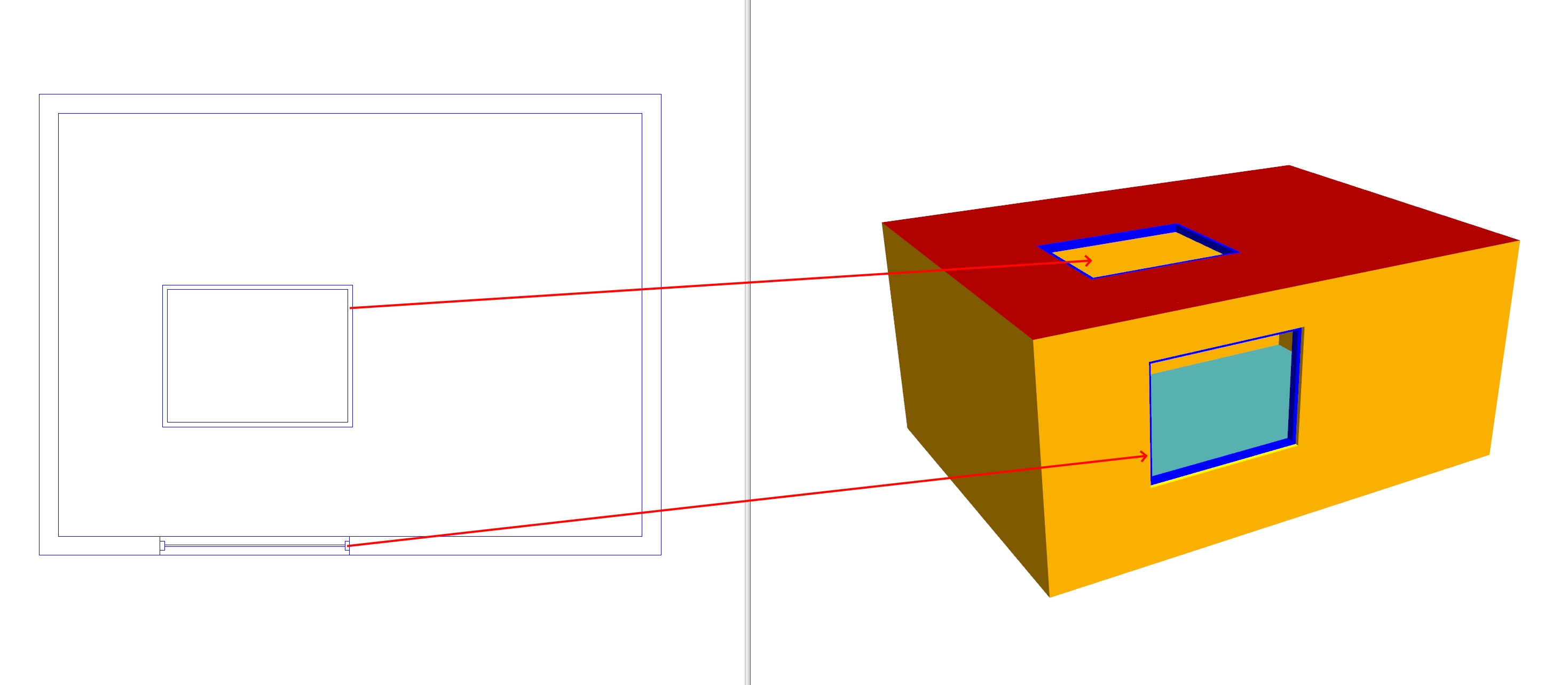
Vertical windows can only be placed within walls, and horizontal windows such as rooflights can only be placed within a space:
Warning
It is essential that windows with the wall placement option are positioned completely within the inner volume of a room. If they aren’t, you’ll get a Windows are not contained within walls error message and the model will be invalid.
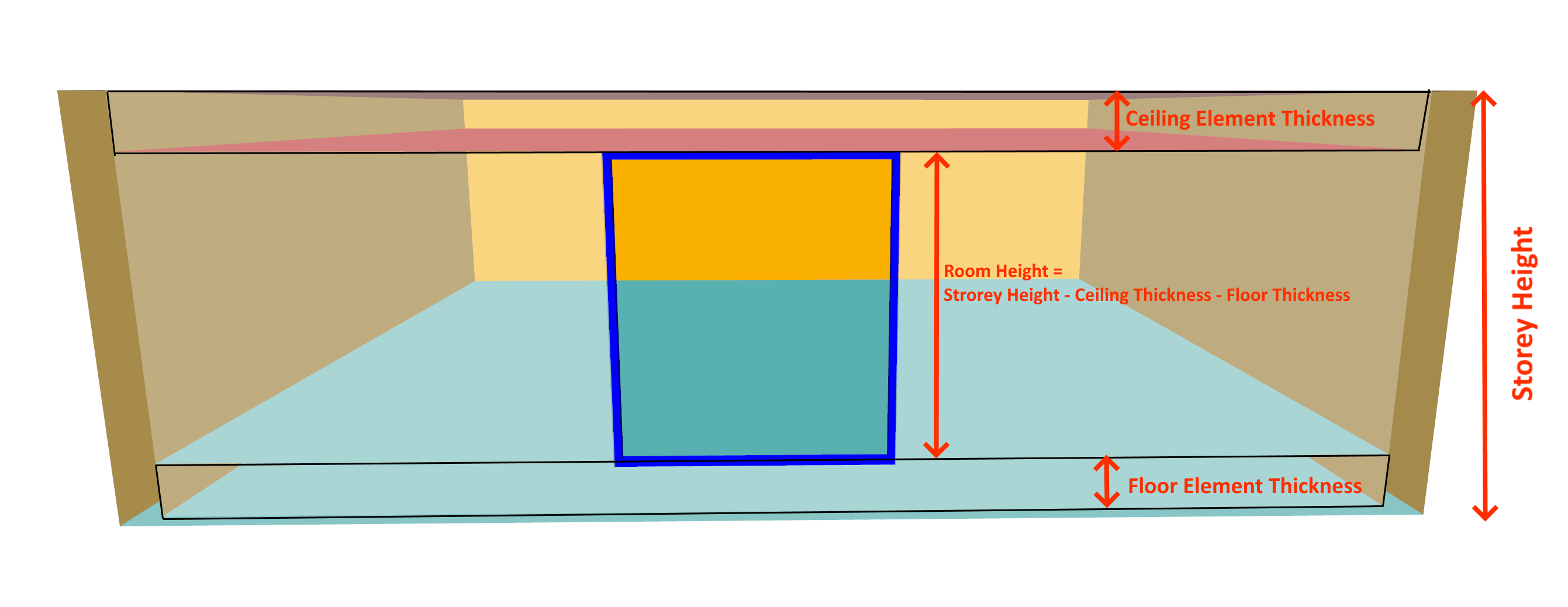
The minimum level of a window or window group must be greater than the thickness of the building element applied to the floor
The level + height of a window or window group must not be greater than the room height, which is given by the storey height minus the thicknesses of the ceiling/floor building elements.
Placed Window Properties
Once windows are placed in the 2D plan view, some of their dimensions can be changed independently without affecting other windows of that type.
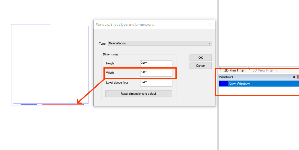
In the above, there is one type of window which is placed twice in the 2D plan view and has two different widths.
To edit the dimensions of a window placement, use the select window tool with a 2D plan view selected.
Fit to wall
You can automatically stretch an individual placement of a vertical window to fill the available wall space:
To fit to wall, use the select window tool and right click on the window and select fit to wall.