Building Elements
Building Elements are used to set the thickness of a surface in the 3D model for walls, ceilings/roofs and floors. This is important for achieving the correct room volumes.
For daylight analysis, Building Elements are used to assign reflectances and transmittances to surfaces in the model.
In the Building Simulator, Building Elements are also associated with thermal characteristics, such as U-Values/ R-Values, specific heat capacity, density, etc. The characteristics are applied by assigning constructions. In this way, Building Elements also allow you to apply different constructions to different surfaces.
Creating Building Elements
Building elements are created using the Model >> Create/Edit >> Building Elements dialog in the ribbon.
You can also access this dialog with the ctrl + E shortcut.
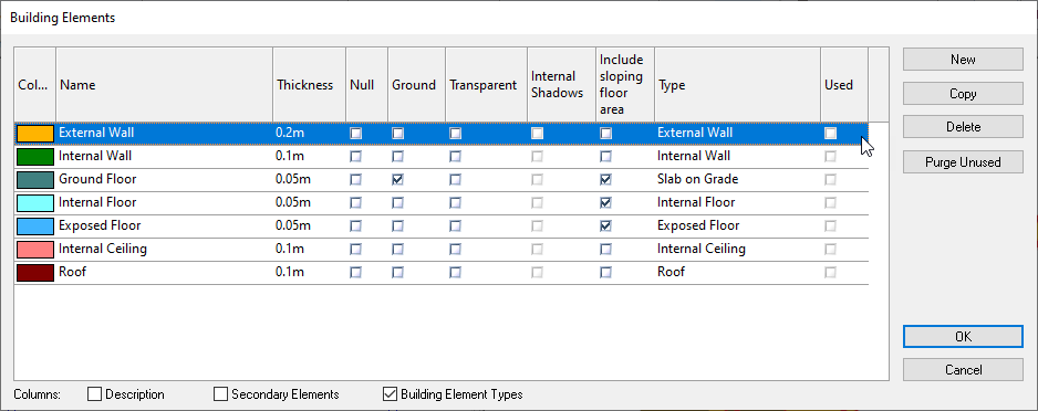
Building Element Colour
You can change the colour of building elements in order to more easily identify them in the 3D analysis view. The colour of a building element is a purely visual property for the modeller, and does not affect the analysis.
Thickness
The thickness of a building element affects the thickness of the surface where it is applied. This can be used to take into consideration the thickness of floor finishes such as carpets.
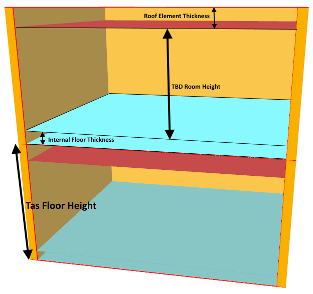
The height of a zone is given by the storey height minus the thickness of the floor and ceiling/roof element.
The thickness of a building element does not affect the thermal properties of the element in the Building Simulator.
In the Building Simulator, Building Elements are assigned constructions which have their own thicknesses that affect thermal properties of a construction.
Null
Null Building Elements are often used for construction lines (when applied to walls), or to indicate that part of a ceiling/floor has no physical surface.
Any number of null Building Elements can be created, which can be useful when part of the null building element will be exposed to the outside.
Warning
If a space has a null surface connected to a space that has not been assigned a zone, or if it is connected to the outside, the 3D modeller will warn you to either zone the adjacent space or mark the zone as external.
Ground
The ground checkbox is used to indicate Building Elements which are in contact with the ground; this usually applies to Ground Floors and Basement Walls.
If a ground building element is exposed in the 3D model, in the Building Simulator, the surface is modelled as being in contact with a material at the ground temperature as specified in the weather file in the Building Simulator.
Solar gain is also removed from surface which have ground Building Elements applied.
If a surface which has a ground building element is adjacent to a zoned space, the ground checkbox has no effect on this surface.
Note
You cannot place a window in a ground Building Element.
Transparent
The transparent checkbox is used for daylight calculations and also affects the distribution of solar energy in a zone with an exposed window if the internal shadows checkbox is applied to that window.
Transparent building elements are often used to model curtain walls, as transparent elements can have a variable light transmittance for daylight calculations.
With regards to the Building Simulator, the transparent checkbox does not force you to apply an transparent construction to that surface. In the Building Simulator, any Building Element apart from Null can be opaque or transparent.
Internal shadows
The Internal Shadows checkbox applies to transparent Building Elements only.
If selected, it allows shadows to fall within the zone on each internal surface, rather than falling on the window and assuming a uniform distribution of energy. The patch of sun that falls on the window is also tracked through any internal null surfaces, but is not tracked through any internal windows.
Note
This option affects the energy analysis only and does not affect daylight calculations.
The transparency of the Building Element does not affect the internal shadows calculation.
Include Sloping Floor Area
Sometimes sloped walls are used to model sloped floors in the 3D modeller. When this happens, the area of the sloped wall (that represents a sloped floor) should be included in the floor area calculation of a zone.
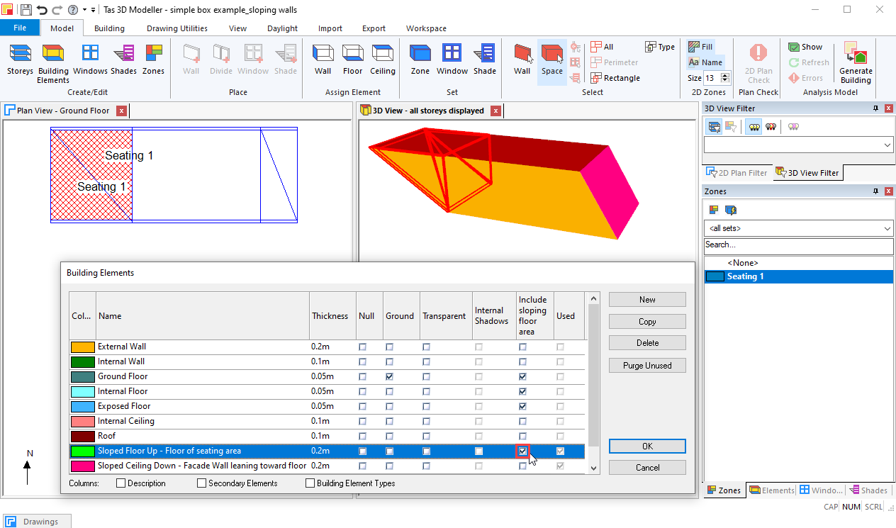
The Include Sloping Floor Area checkbox ensures that surfaces with this building element have their area added to the total zone floor area.
Type
The Building Element type is used for:
Daylight calculation default reflectances/transmittances
Auto-assigning constructions in the Building Simulator
Set Building Element types in the regulations studios
The effect of the Building Element type can be overridden wherever it is used.
Used
The used checkbox cannot be changed by the user, but indicates whether a building element has been used at least once in the 3D model. This helps identify unused elements which can safely be deleted.
Assigning Building Elements
Building Elements can be explicitly assigned in three ways:
When drawing walls
Using the Assign tools
Using the Select tools >> properties
When drawing walls, whichever Building Element is selected in the Elements panel will be used for those walls.
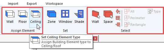
Assign Tools
The Set Wall Element , Set Ceiling Element and Set Floor Element tools can be used to change the Building Element type. You can do this by selecting the element in the Building Elements panel and clicking on the corresponding surface/ space in a 2D or 3D view to chage that surfaces building element:
Select Tools
The select tools can be used to change the Building Element by right clicking on the selected element and selecting properties:
This applies to Walls, Floors and Ceilings/Roofs.
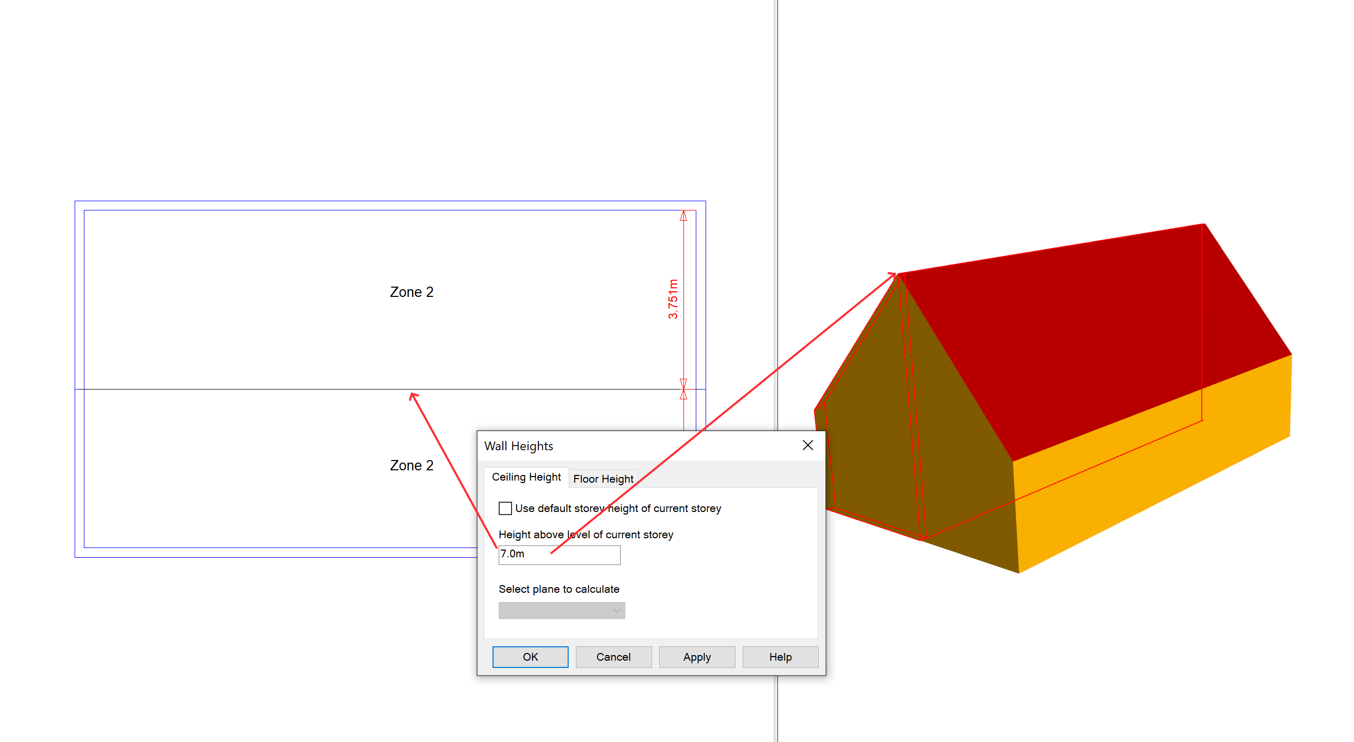
Null walls
Null walls are often used to create separate surfaces for pitched roofs:
They can also be used to assign more than one zone to a space, which is useful when modelling large spaces or following UK Building regulations zoning rules, or LEED 90.1 perimeter zoning rules.
Null walls can be used to sub-divide a space for creating voids.
Null walls can also be used as a surface on which shades can be placed.
Null ceilings/floors
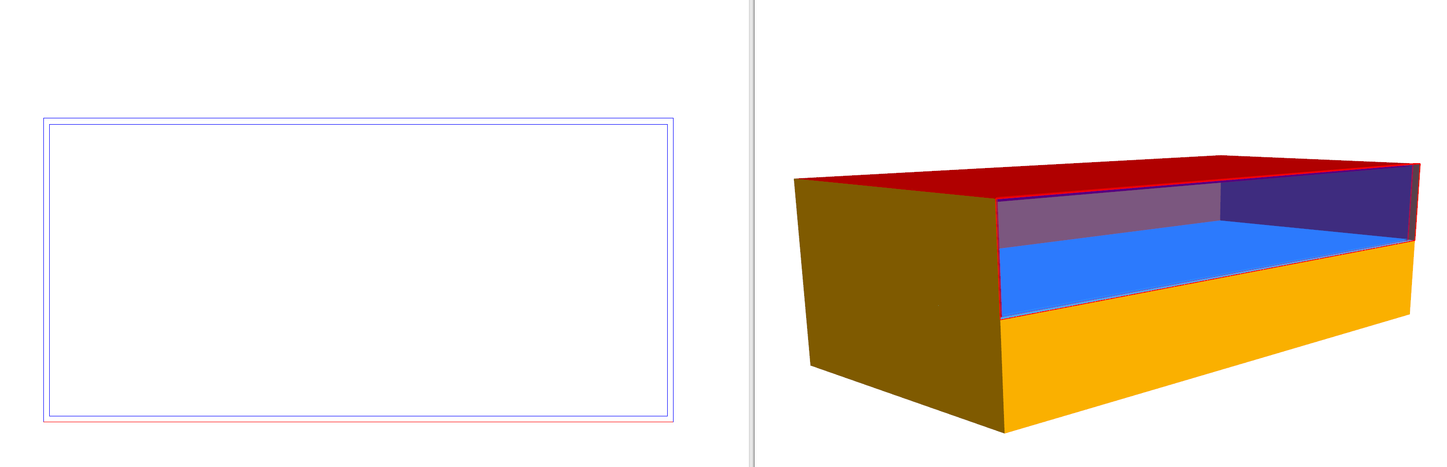
If a null ceiling and null floor overlap, there is no physical surface between the spaces in the model. This is useful for modelling double height spaces and atria:
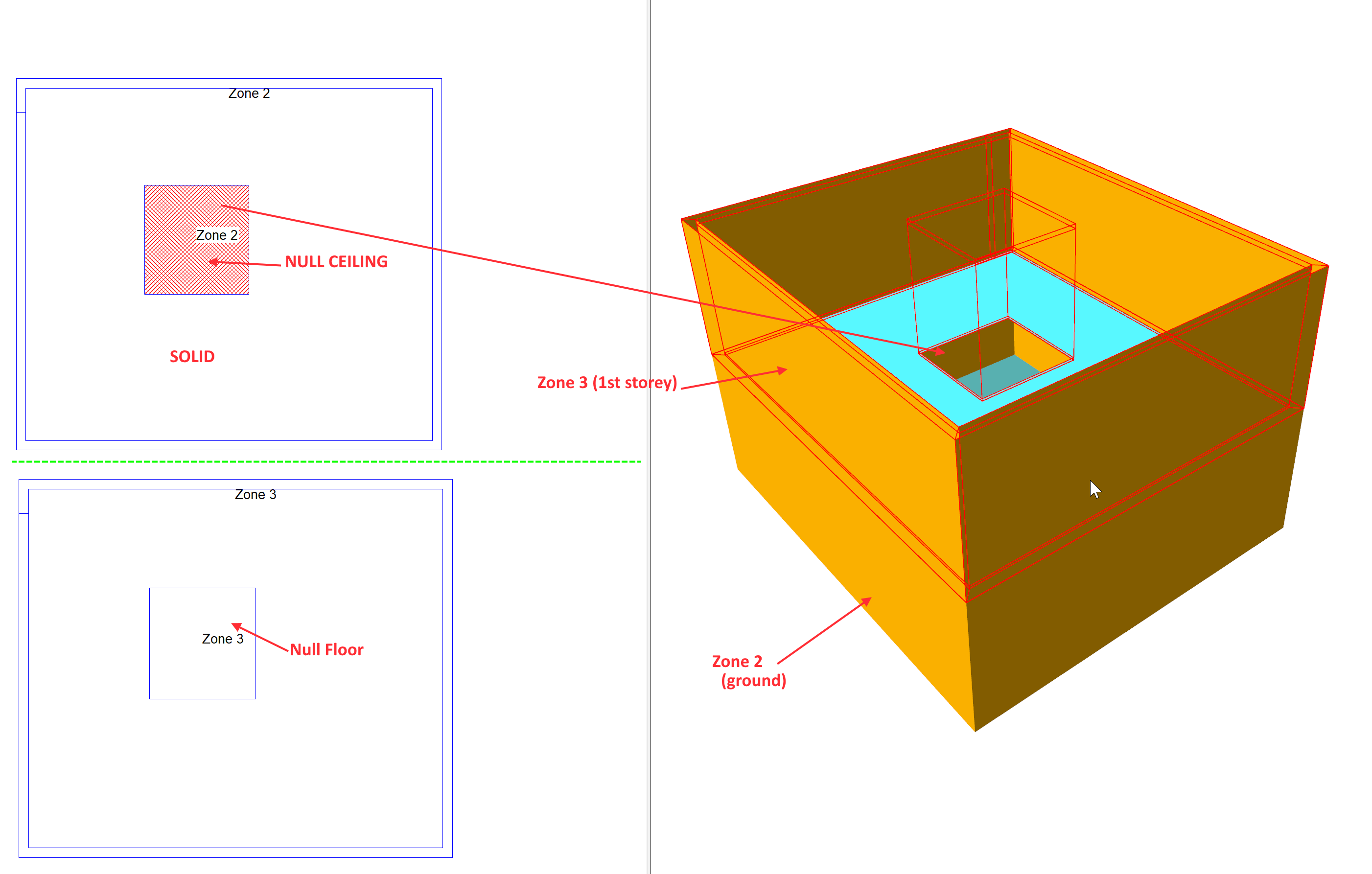
In the above, a part of the partition between the ground floor and first floor have been removed using a null ceiling on the ground floor, and a null floor on the first floor.
Note that, in the above diagram, the roof has been removed so you can see inside.
If a null ceiling is in contact with a non-null floor, the partition will be present and the 3D modeller will warn you when creating the analysis model in case it is unintentional.
The Default Building Element
The default Building Element represents an automatic Building Element that changes to either External Wall or Internal wall when drawing walls, or Roof, Internal Floor/Ceiling or Ground Floor when setting ceiling/floor elements.
The default Building Element enables you to draw a floor plan quickly without explicitly having to set the outer walls to External Wall, and internal partitions to Internal Wall.
It does not appear in the create/edit dialog, but does appear in the Building Elements panel.
Secondary Elements
Secondary Elements are a convenient way of modelling the situation where a surface may be composed of multiple constructions.
For example, the facade of a building may be 80% glazed; to model this, we could use the Secondary Element feature:
Create a transparent Building Element (for the glazing)
Add a 20% Secondary Element on the transparent Building Element set to External Wall
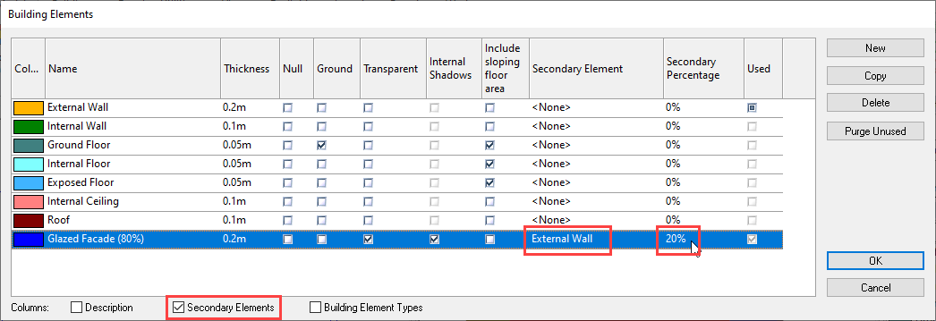
To enable the use of Secondary Elements, you must tick the Secondary Elements checkbox at the bottom of the create/edit Building Elements dialog.
You can also set the Secondary Element of a Building Element to be another Building Element with a Secondary Element. This can be useful if you want to model, for example, an 80% glazed facade/ 20% external wall and the glazed facade is 90% glazing and 10% frame.
Note
Internal shadows cannot be calculated for Secondary Elements, as the Secondary Element is assumed to be uniformly distributed across whichever surface it is applied to.