2D Views
Getting familiar with the tools in the 3D modeller will help you create models more quickly and easily.
The tools in this section primarily apply when a 2D plan view is selected.
Wall Alignment
The wall alignment options that apply when drawing and merging walls are:
Left
Centre
Right
These options relate to the edge of the wall that will be placed directly under the mouse cursor when you click when drawing walls:
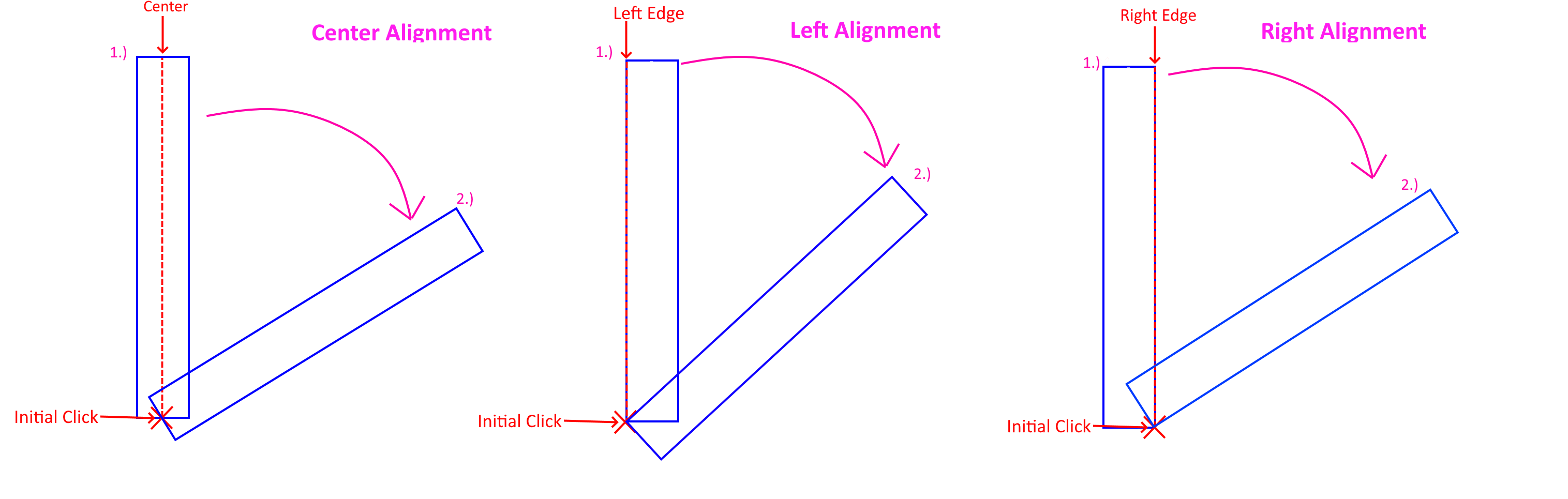
With the Right Alignment option:

When two walls meet, they will also snap together along the selected alignment option if they are misaligned - e.g. for right alignment:
Note
It is highly recommended you model using the center wall alignment option switched on.
Using the centre wall alignment option generally results in walls that align easily.
Align walls on input
The Align Walls on Input option ignores the Left/Center/Right alignment option and attempts to align based on the wall that is being connected to.
Merge walls on delete
The Merge Walls on Delete option determines whether two walls will become one when a wall that forms a join is deleted:
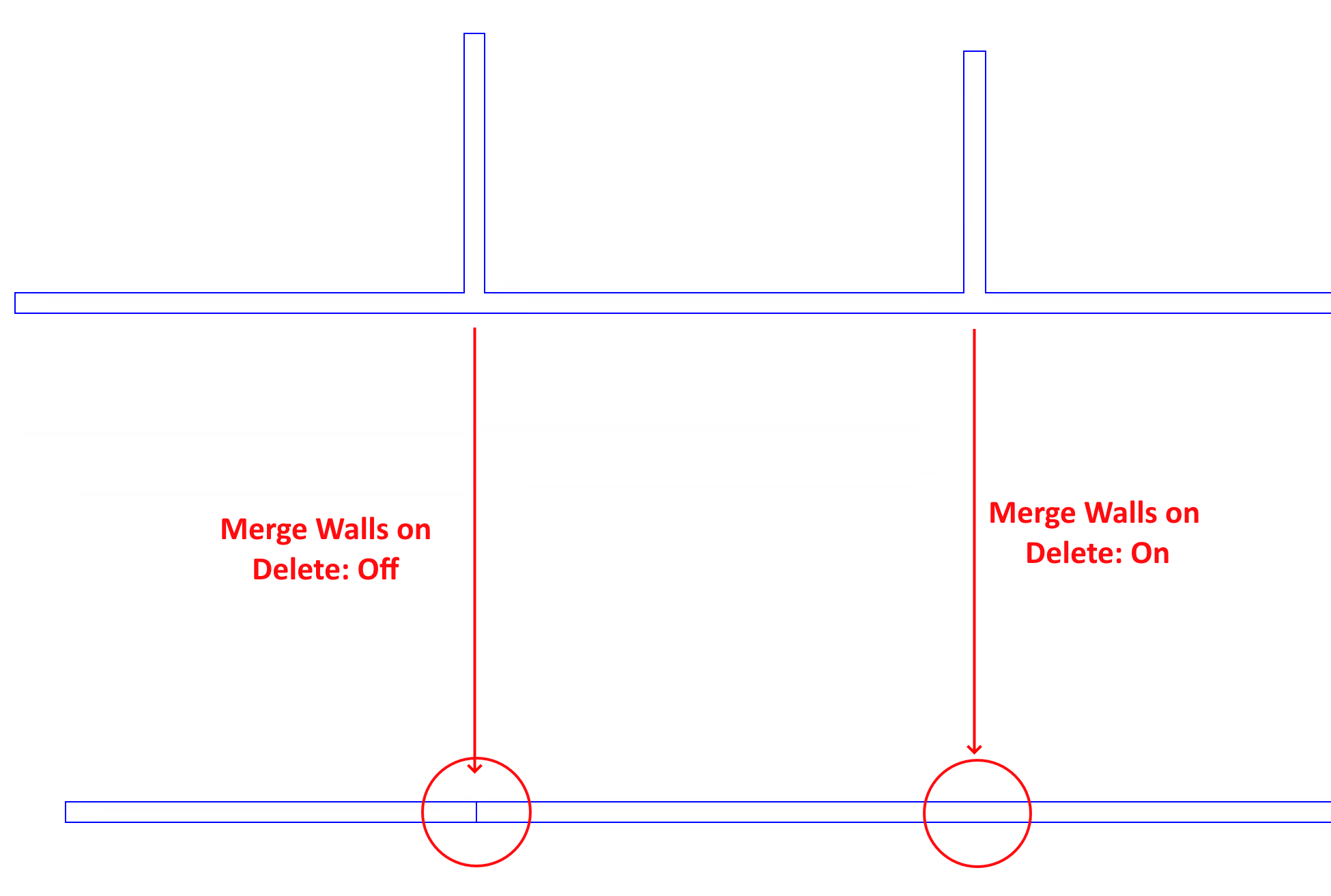
This option is usually left switched on.
Perpendicular to & Parallel to
If you wish to place walls parallel or perpendicular to an existing wall, you can do so by selecting the wall with the select wall tool, right clicking, and selecting the corresponding option.
To stop drawing walls that are parallel or Perpendicular, you can either use the select wall tool and right click on the same wall to select the option, or you can switch to a different tool before returning to the place wall tool.
These options can be useful when you wish to place a small number of walls relative to another. For large quantities, set the drawing grid relative to the existing wall.
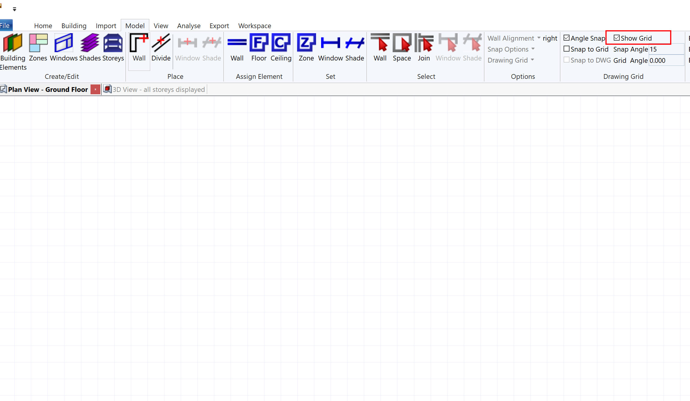
Grid Setup
When placing walls in the 3D modeller, the grid is a set of adjustable guidelines you can use to help make the modelling process easier.
You can make the grid visible by checking the Show Grid checkbox in the model >> drawing tab of the ribbon:
The grid can be rotated by changing its angle, and the size of the squares can be changed by altering the grid spacing.
The Grid Setup dialog can be used to alter some extra options:
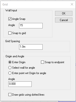
The Enter Origin checkbox moves the grid to wherever you click next in the 2D plan view. This can help you align the grid with a very specific point. The Snap to endpoint makes it easy to position the origin on the endpoint of a wall.
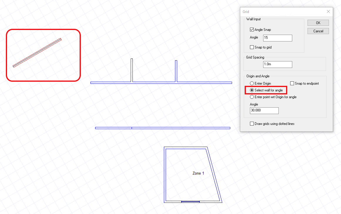
The Select wall for angle option allows you to set the grid angle by clicking on a wall. You can achieve the same effect by selecting a wall, right clicking and selecting Set grid angle:
Snap Options
There are several Snap Options in the 3D modeller which are designed to make it easier to place walls. They are:
Grid Snap
Angle Snap
Drawing Snap
If you turn off all of the snap options, you can place walls in any position – this can lead to walls which are slightly misaligned, and can make it more difficult to define planes.
Warning
Placing walls with all the snap options off can make it hard to create planes, and can reduce the quality of the analysis model!
One occasion where it might be useful to turn off the Snap options is if you are placing a wall which you will then use to orient the grid.
Grid Snap
Grid Snap can be turned on and off via model >> Drawing Grid >> Snap to Grid in the ribbon.
With this option switched on, walls will prefer to be aligned with the grid so it’s recommended that you make the grid visible when using this option. The grid visibility can be toggled via model >> Drawing Grid >> Show Grid in the ribbon.
This option tends to be useful if you’re placing walls without reference to a drawing.
Angle Snap
Angle Snap is enabled by default, and is the recommended snap option when working in the 3D modeller.
It can be enabled via model >> Drawing Grid >> Angle Snap in the ribbon.
With angle snap enabled, placed walls will tend to prefer placements that are the angle of the grid plus multiples of the angle snap angle.
For example, if the grid angle was 10° and the angle snap angle was 15°, the walls would prefer angles 10°, 10°+15°, 10°+15°+15°…
The default snap angle of 15° is quite useful as it allows for common wall placements. Most real walls tend to be placed at 90° angles to one another, and if your grid is aligned with your walls, this will be one of the preferred angles.
Drawing Snap
The drawing snap option allows for placed walls to align themselves with imported 2D DWG files that are visible in the 2D Plan View.
If your reference drawing does not contain any overlapping walls and is accurate, this can be a good option.