gbXML
Green Building XML (gbXML) is a file format designed for interoperability between CAD and building simulation software. More information about gbXML can be found here.
The Tas 3D modeller can import and export gbXML files.
When importing gbXML files in Tas, the 3D modeller will identify common problems with gbXML files and automatically repair many of them making it an incredibly powerful BIM tool.
Note
If you re-import a gbXML file to update the geometry, any edits you have made to the imported model will be preserved and automatically applied to the new model, Building Element assignments, for example.
Pre-requisites
Before you produce a gbXML file from your chosen package to import into Tas, it is important to ensure your model has been set up to produce good quality gbXML files.
If you are exporting a gbXML file from Revit, please see our Revit gbXML Guide for advice regarding how to correct common mistakes with Revit models that may make them unsuitable for energy analysis.
Importing gbXML
A gbXML file is usually imported into a new 3D modeller file that does not contain any existing geometry. It is possible to import to update an existing imported model, in which case the
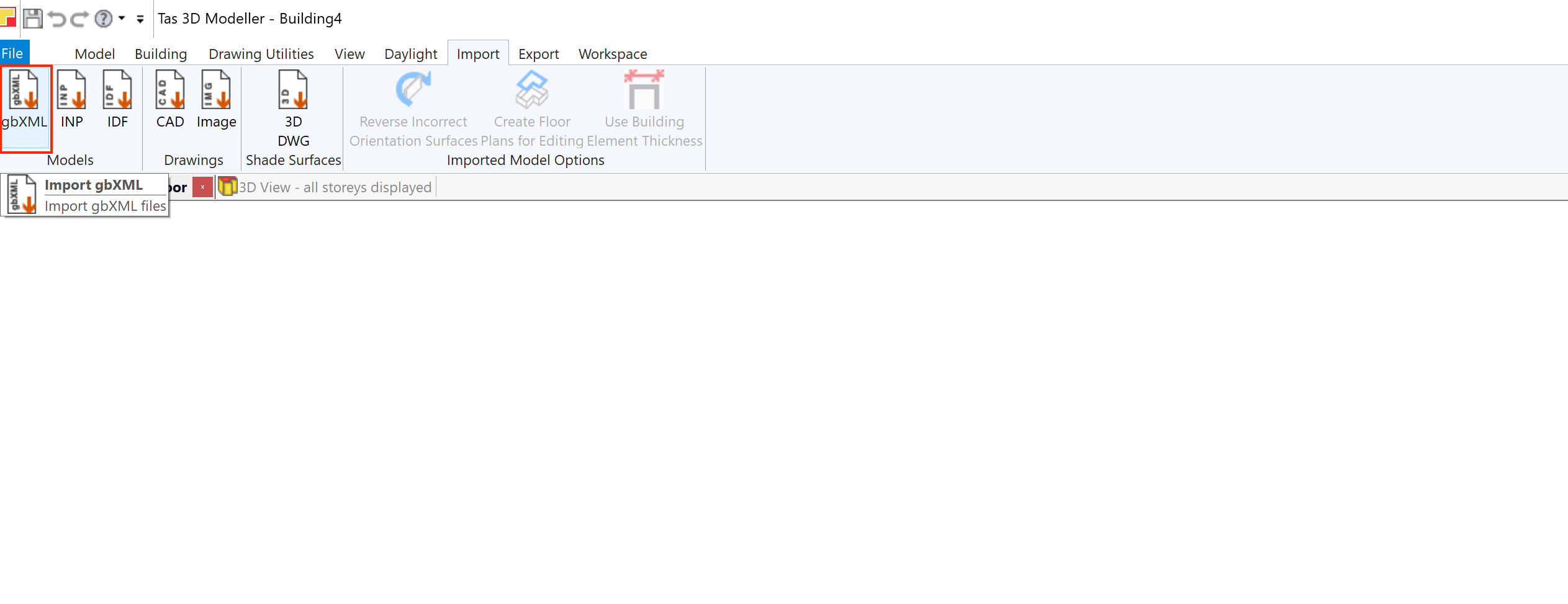
To import a gbXML file, go to Import >> Models >> gbXML in the ribbon:
Select your gbXML file and press open. You’ll then be presented with the gbXML Import Report, the gbXML Import Options dialog and a Preview View of your gbXML file.
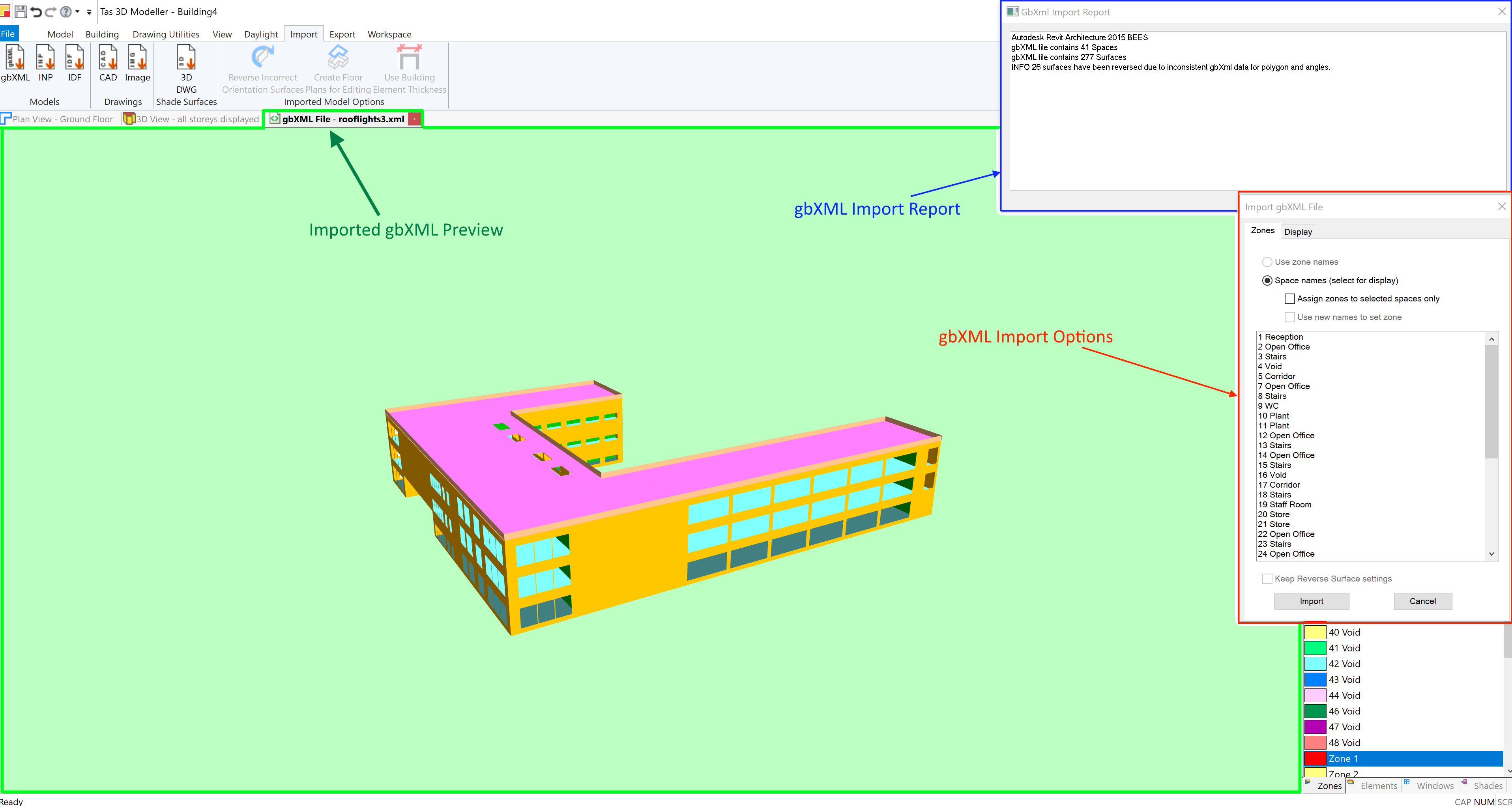
The Import Report contains information such as:
The source of the gbXML file
The number of identified spaces
The number of identified surfaces
Automatic corrections/repairs made by the 3D modeller
At this stage you should check that the number of spaces found in the gbXML file match your expectations.
You should also use the Display tab in the gbXML Import Options to alter the gbXML Preview View to make it easier to visually inspect the model.
Once you have inspected the gbXML Preview, press Import to complete the process.
Warning
It is very important to inspect the model for import errors and artifacts. If there are errors in your model, consult the documentation for the software producing the gbXML file. If you are using Revit, see our Revit gbXML training material in addition to the Revit documentation.
Display Options
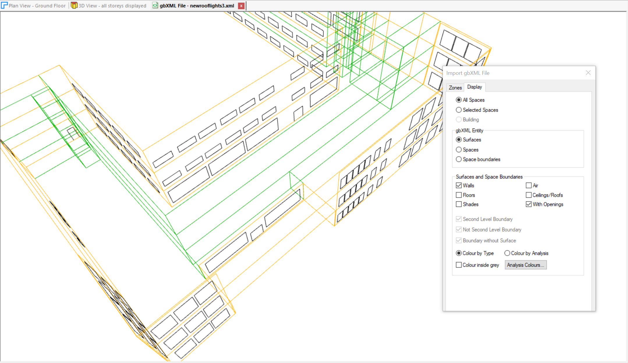
The following gbXML display options are available prior to completing the gbXML import process:
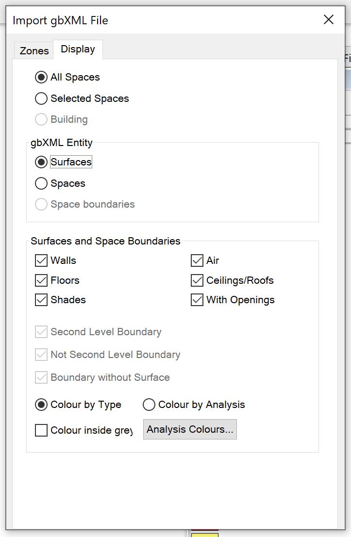
The gbXML Entity option allows you to switch between viewing the surfaces in the gbXML file and the spaces:
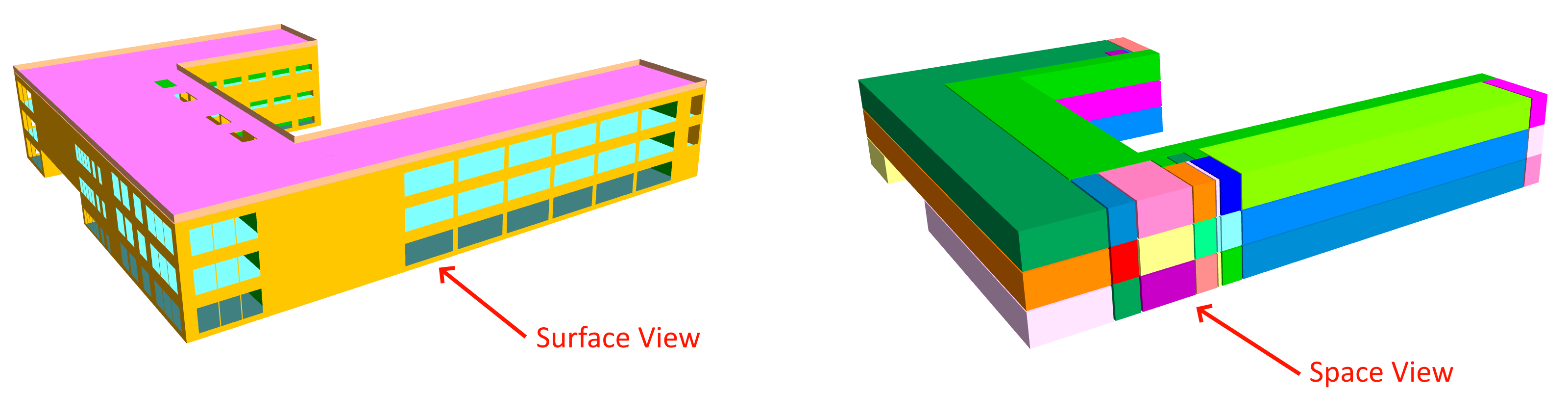
Using these options you can check for missing surfaces, extra/misshapen surfaces and incomplete spaces. Usually there should be no gaps between adjacent spaces. You can inspect individual spaces by selecting one or more in the list on the Zones tab and using the Selected Spaces option.
When you have the Surfaces displayed, you can also alter the Surface and Space Boundary display options. You can examine each of the following options in isolation:
Walls
Floors
Shades
Air
Ceilings/Roofs
With Openings
This will allow you to check that the expected elements are in the correct place, and there are no unexpected air gaps.
You can use the Colour inside grey option to quickly visually identify surfaces which have an incorrect orientation – if you see grey on the outside of any external surfaces, the orientation of those surfaces are incorrect. If a single space is displayed and a surface is coloured grey on the outside of the space, this also indicates an incorrect orientation. See below for methods to correct such surfaces.
You can also colour by Analysis Colours, which will allow you to identify surfaces corresponding to the following analysis types:
Ground Floor
Exposed
Internal
Link
Adiabatic
gbXML Shades
If any of the surfaces have the wrong types assigned in the gbXML file and you do not have the ability to correct the source and re-export, see below for possible methods to correct such surfaces after importing the gbXML file. If you update the gbXML file and need to re-import it, these changes will be preserved and applied to the newly imported model.
gbXML vs Tas3D Geometry
When working with gbXML imports rather than purely native Tas3D geometry, there are some differences it is useful to be aware of.
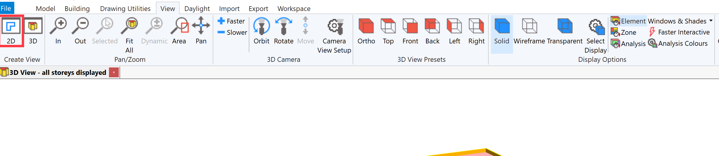
Firstly, by default, there is only a single 3D view. Although there are storeys, there are no floor plans and initially no 2D plan views for editing:
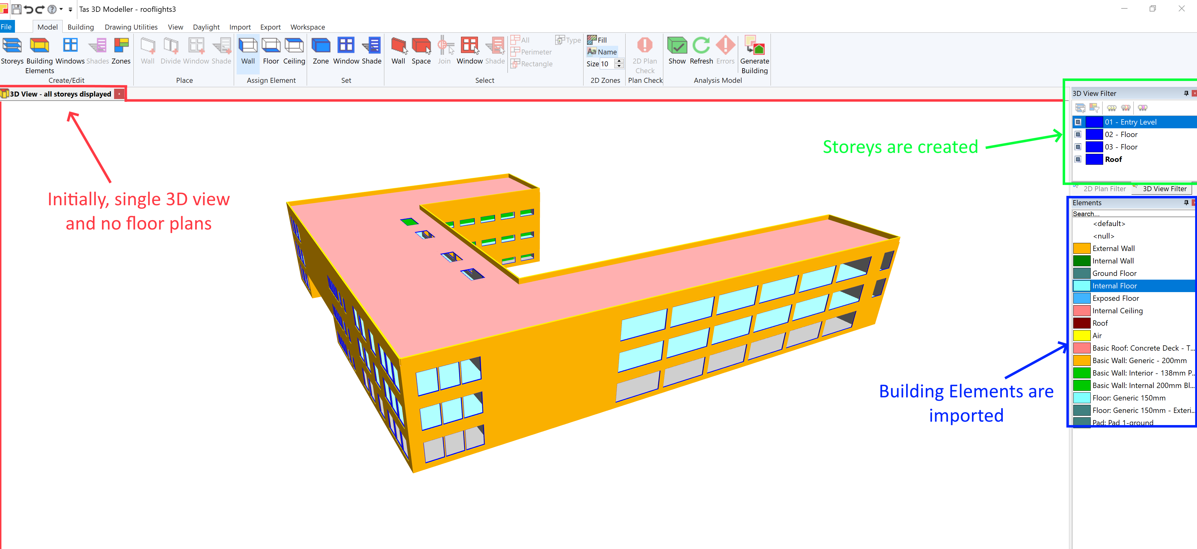
You can select storeys to be included in the view using the 3D View Filter.
You cannot change the positions of imported walls, floors and ceilings or delete them. Although shade surfaces imported from the gbXml file can be deleted.
You can create additional regular storeys in the 3D modeller by placing walls, windows and shades. These storeys are then merged with the imported gbXml model to create one analysis model. This is used, for example, to create (external) zones for shading purposes as detailed below.
2D Floor Plans can optionally be created, which allow further limited editing, usually to sub-divide spaces if further zoning is required. See below.
Surface and Space Selection
Imported surfaces can be selected in the 3D view for limited editing using Model >> Select >> Wall. All imported gbXml surfaces, including floor and ceiling surfaces, are classified as a Wall for this purpose. An individual surface can be selected by clicking on it.
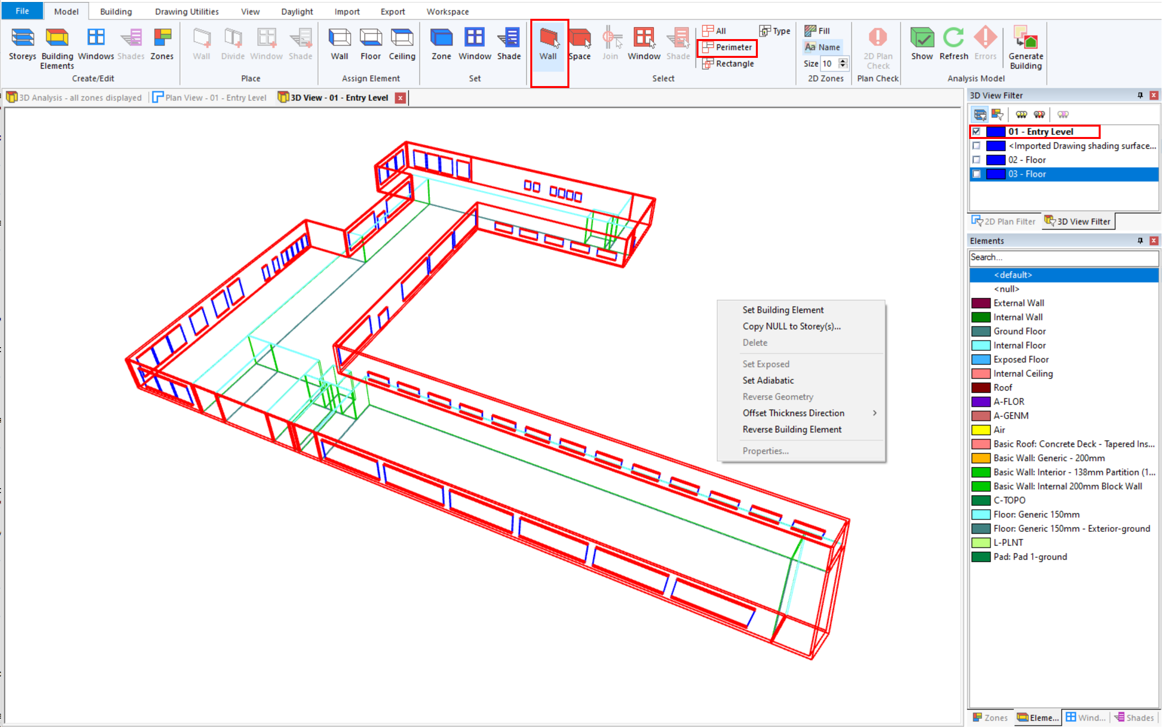
Alternatively use the options in Model >> Select, by Type for example. Selection by Perimeter selects all external wall surfaces as shown below and the available menu options. Note that the view can be filtered according to the gbXml storeys.
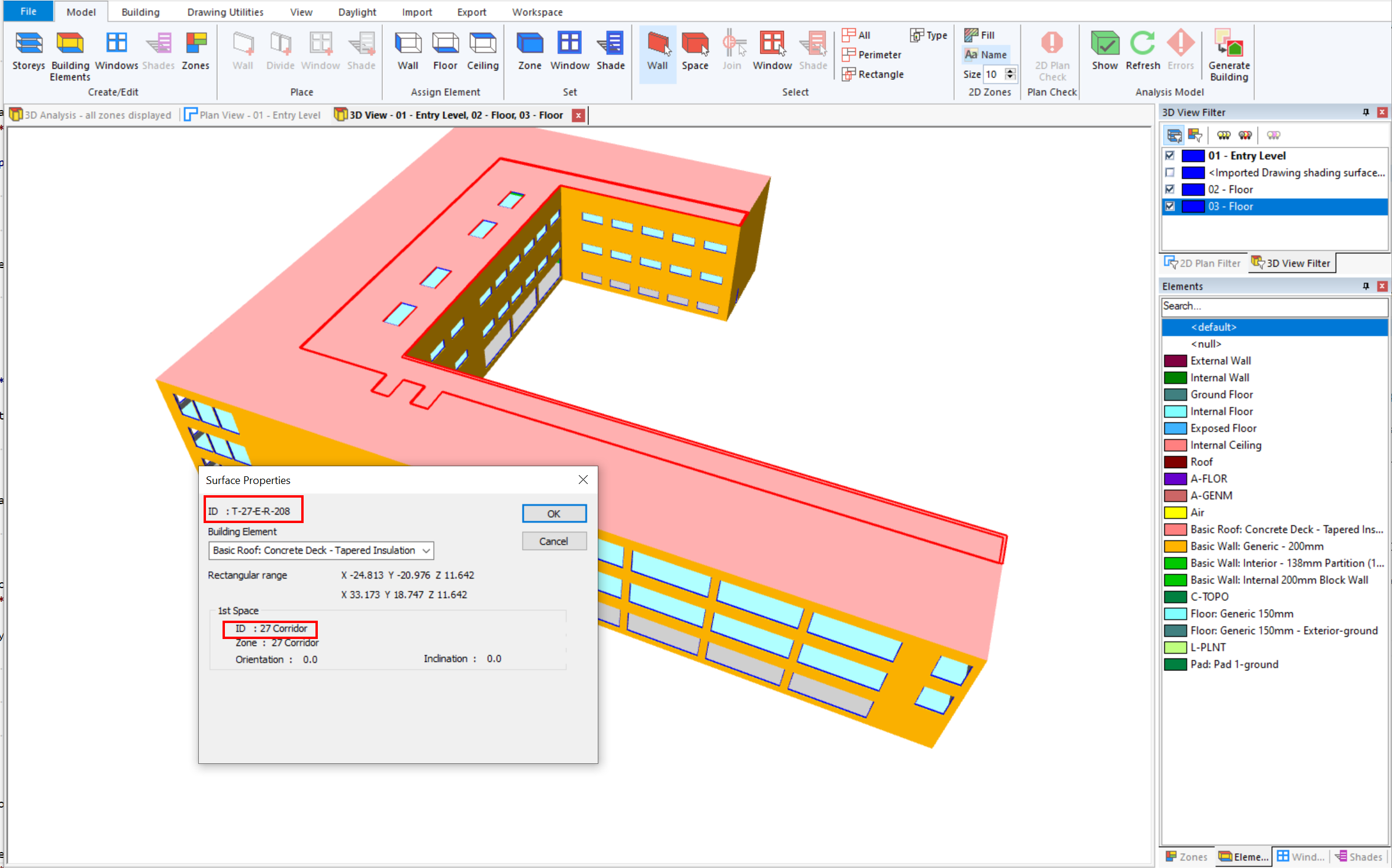
The Properties… option is available if one surface is selected and shows attributes such as the surface ID which is taken from the gbXml file. Note that the ID cannot be changed. The attributes of one or two adjacent spaces are shown, depending on whether the surface is external or internal to the model.
Imported spaces can also be selected in the 3D view using Model >> Select >> Space. This provides options such as changing zone assignments from those set on import and assigning tags to zones.
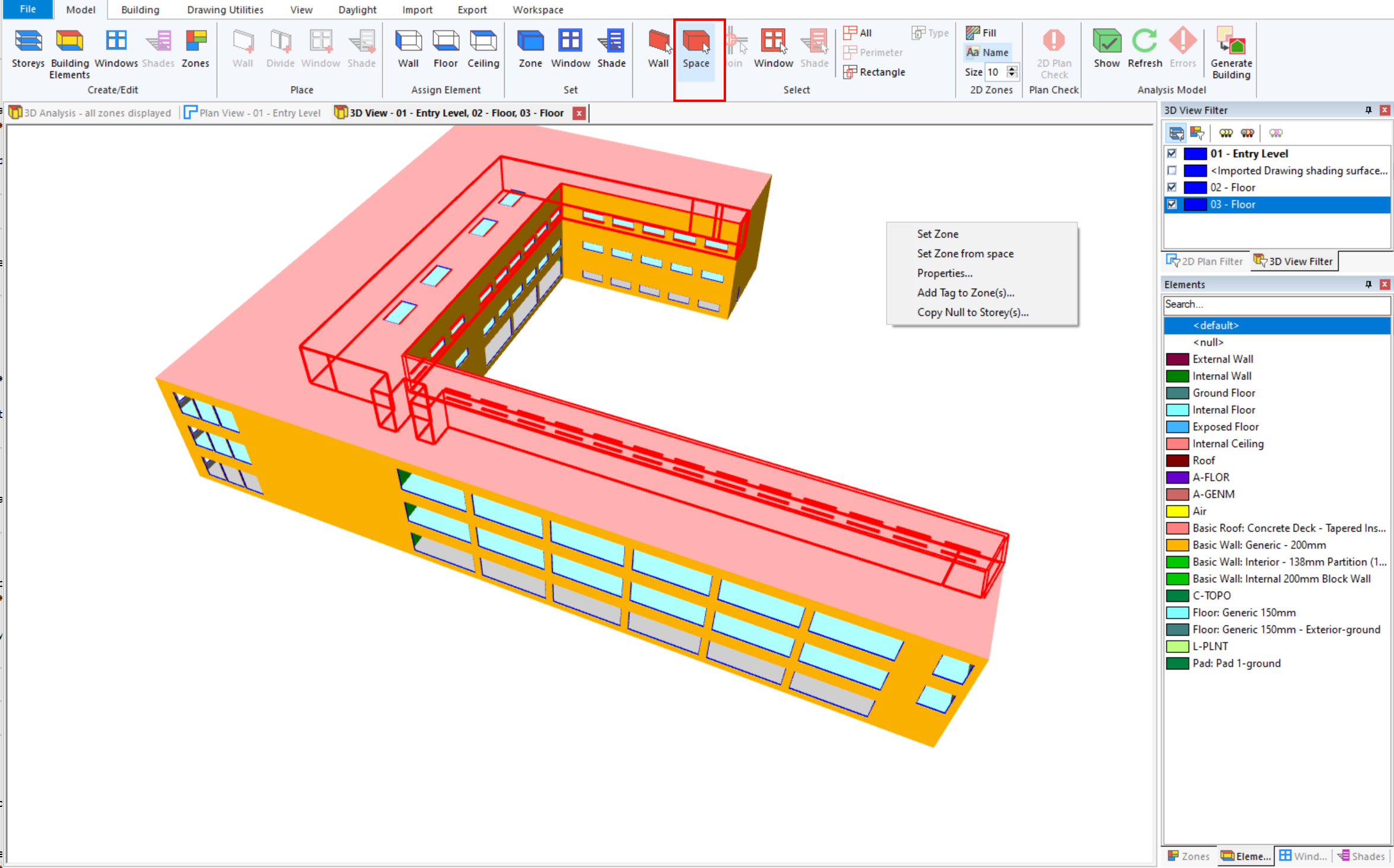
The option Set Zone from space resets a zone assignment back to a zone with the name of the space.
The Properties… option is available if one space is selected and shows attributes such as the space ID which is taken from the gbXml file.
Building Elements
Building elements are created and assigned to the imported surface depending on the contents of the gbXml file. The naming convention will be one of the following
gbXml Construction name if such entities are present in the gbXml file, usually with Layers and Materials, and one is assigned to each gbXml surface
gbXml surface type name may be used to create elements with names such as Exterior Wall, SlabOnGrade, Roof, Interior Wall etc
gbXml CADObjectID name (Revit gbXml files only) will be used to create elements with names such as Basic Roof: Generic - 400mm or Basic Wall: Generic - 300mm
The element assigned to any imported surface can be changed using the usual options once a surface is selected.
Using Building Element Thickness
The thickness of a surface, that is a wall, a floor etc is not specified directly in a gbXml file. The surfaces are shown with zero thickness in the Preview View of the gbXml file. Here is a wireline view of just the walls:
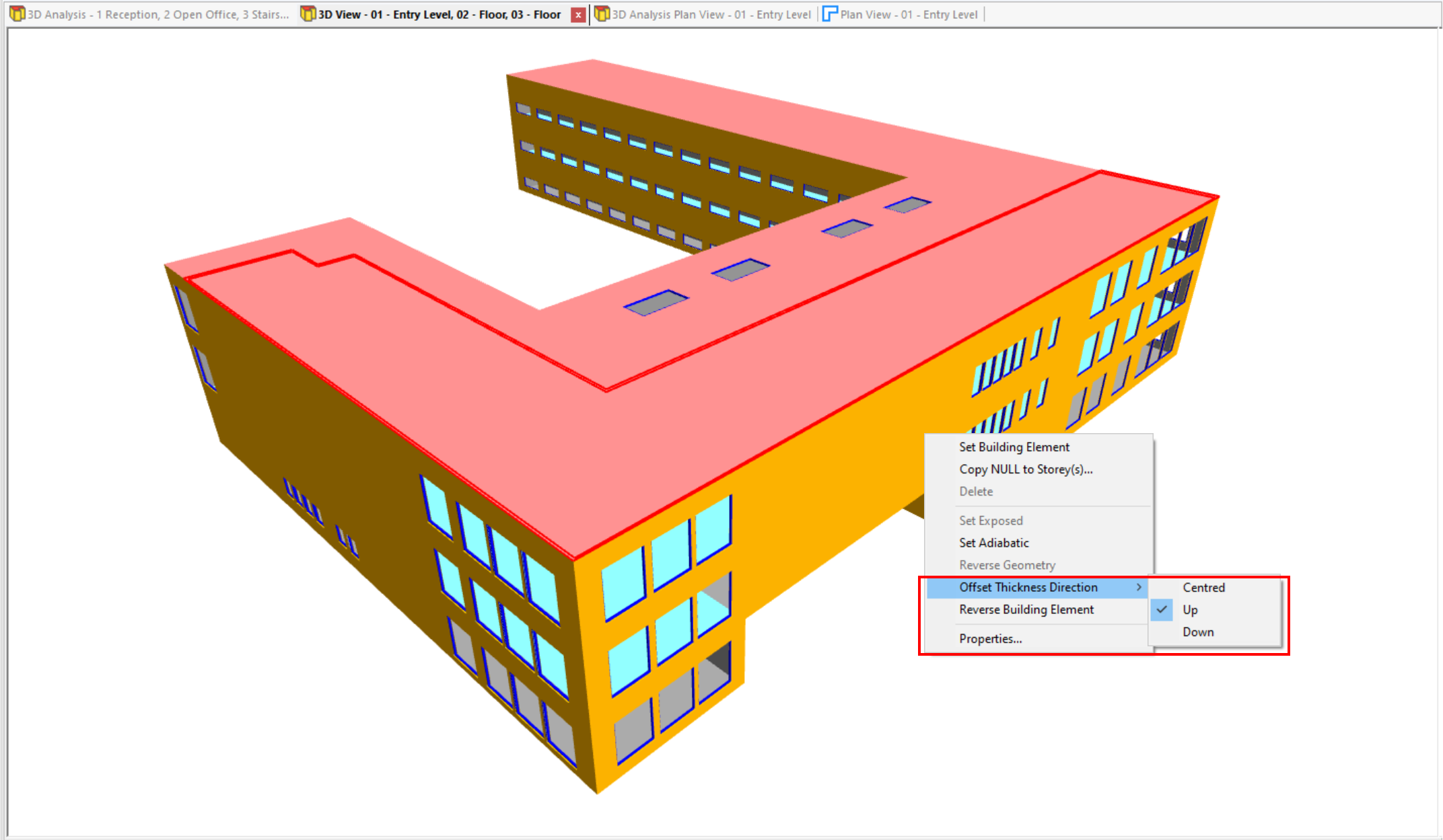
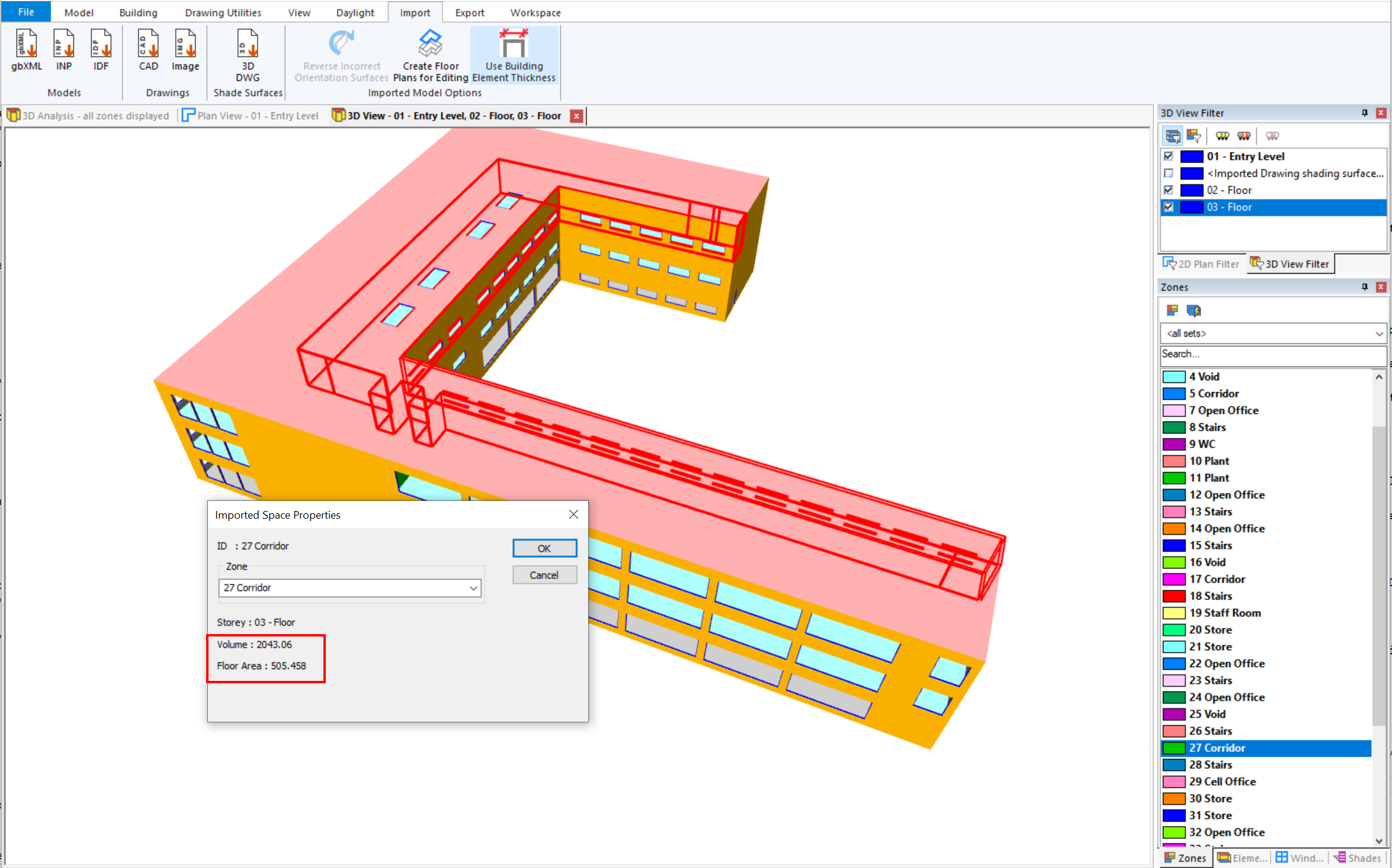
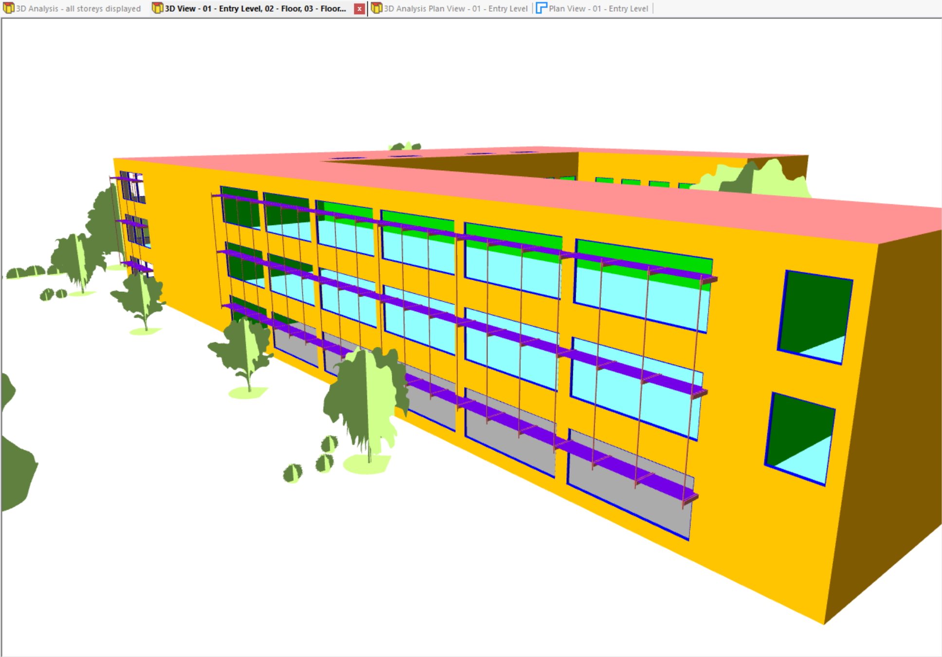
There is an option on the ribbon Import >> Imported Model Options >> Use Building Element Thickness which controls how the imported surfaces are represented. This is selected by default and offset surfaces are created, dependent on the thickness of the assigned building element. A 3D view will show the walls as having a thickness as demonstrated below for a 3D Analysis Plan View
With this option selected, the areas that are exported to the Building Simulator will be the average of the areas of the offset surfaces. Also the internal floor area and volume of each space will be calculated using the inside offset surfaces. Additional advantages are that daylight calculations are performed with less light leakage through gaps in the surfaces and window overhangs are accounted for in shading calculations.
Refreshing the Analysis Model will apply any changes to an element’s thickness.
The direction of the thickness to create offset surfaces can be set for floors and roofs as either entirely up or down from the original surface or centred around it. The default is down for floors and up for roofs. The option is available for such selected surfaces as shown. For walls it is assumed that the original gbXml surface is positioned on the centreline of the wall.
Note
If this option is not selected, the floor area and volume of a space are taken directly from the gbXml file, which by definition should be the interior area and volume. This can be checked by looking at the properties of a selected space.
Modifying and Making Corrections to the Imported Model
The following describes menu options that may be available for selected imported surfaces. Their availability will depend on the attributes of the surface when imported.
Set Adiabatic
This option is available for all surfaces adjacent to just one space. By default, when this option is not selected, these surfaces would be exposed in the building data generated for analysis. If the gbXml model represents just part of a whole building, such surfaces can be identified as adiabatic instead in the building data by selecting this option.
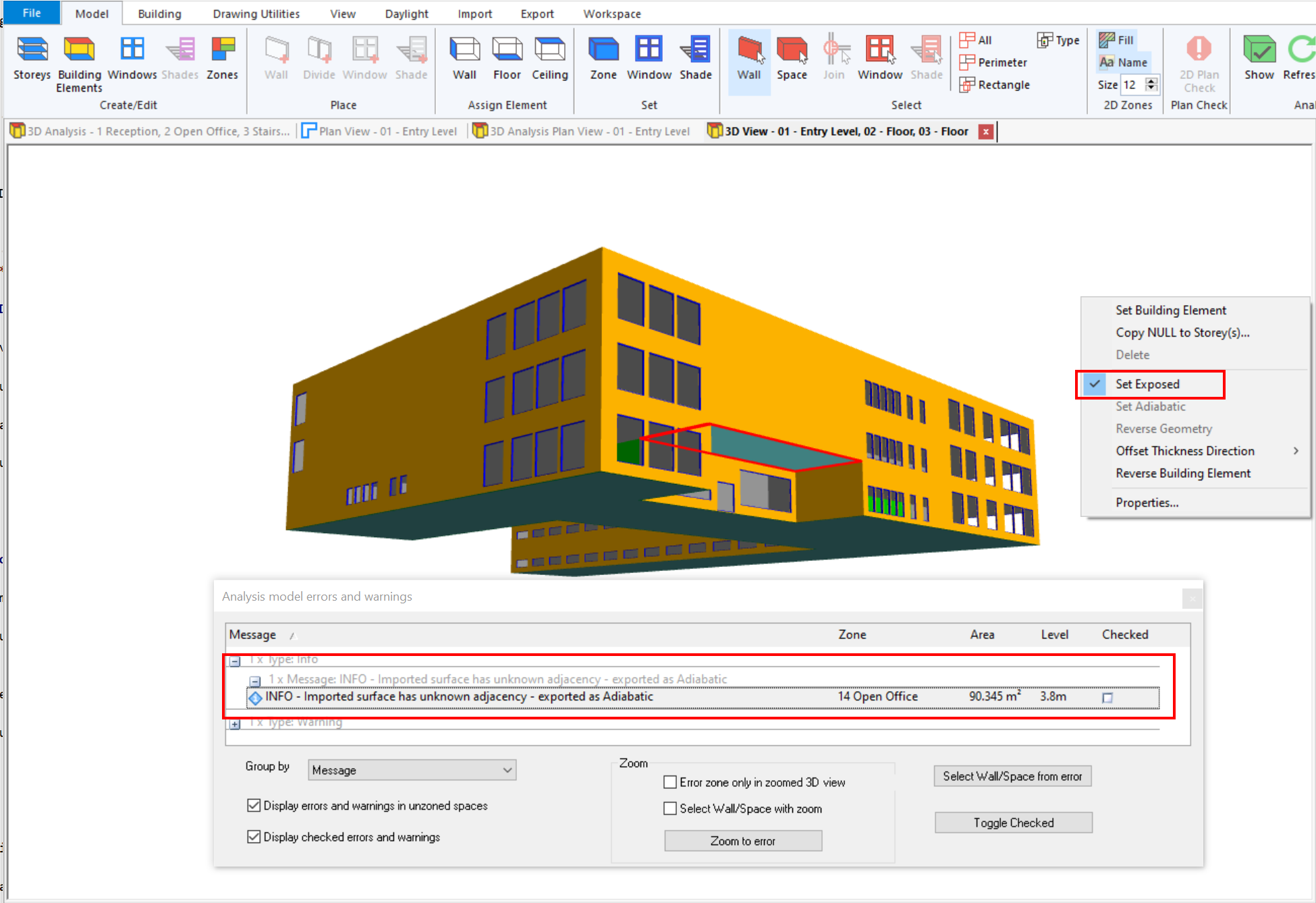
Set Exposed
This option is only available for those surfaces when it is unknown, as specified in the gbXml file, whether the surface is adiabatic or exposed.
Note
This can occur with gbXml files generated by Revit only. In this case, the gbXml file indicates a surface is Internal to a space when in fact it lies on the boundary of the space.
By default the surface is identified as Adiabatic. If the other side of the surface is adjacent to a different space then this is the correct attribute to be used. However if it is known that the surface is actually on the boundary of the building then it can be defined as Exposed.
For such surfaces, a message is added to the Analysis model errors and warnings list, as shown below. To change the attribute to be Exposed, select the surface in a non-analysis 3D View and select the Set Exposed option.
Note
The Set Adiabatic option is not available for these surfaces. De-selecting the Set Exposed option resets the surface to be Adiabatic.
Reverse Geometry
This option is only available for surfaces of spaces that may be incorrectly defined in the imported gbXml file. It is checked on import whether a space is enclosed by correctly oriented surfaces. Warnings are shown for such spaces in the Analysis model errors and warnings list, as shown below.
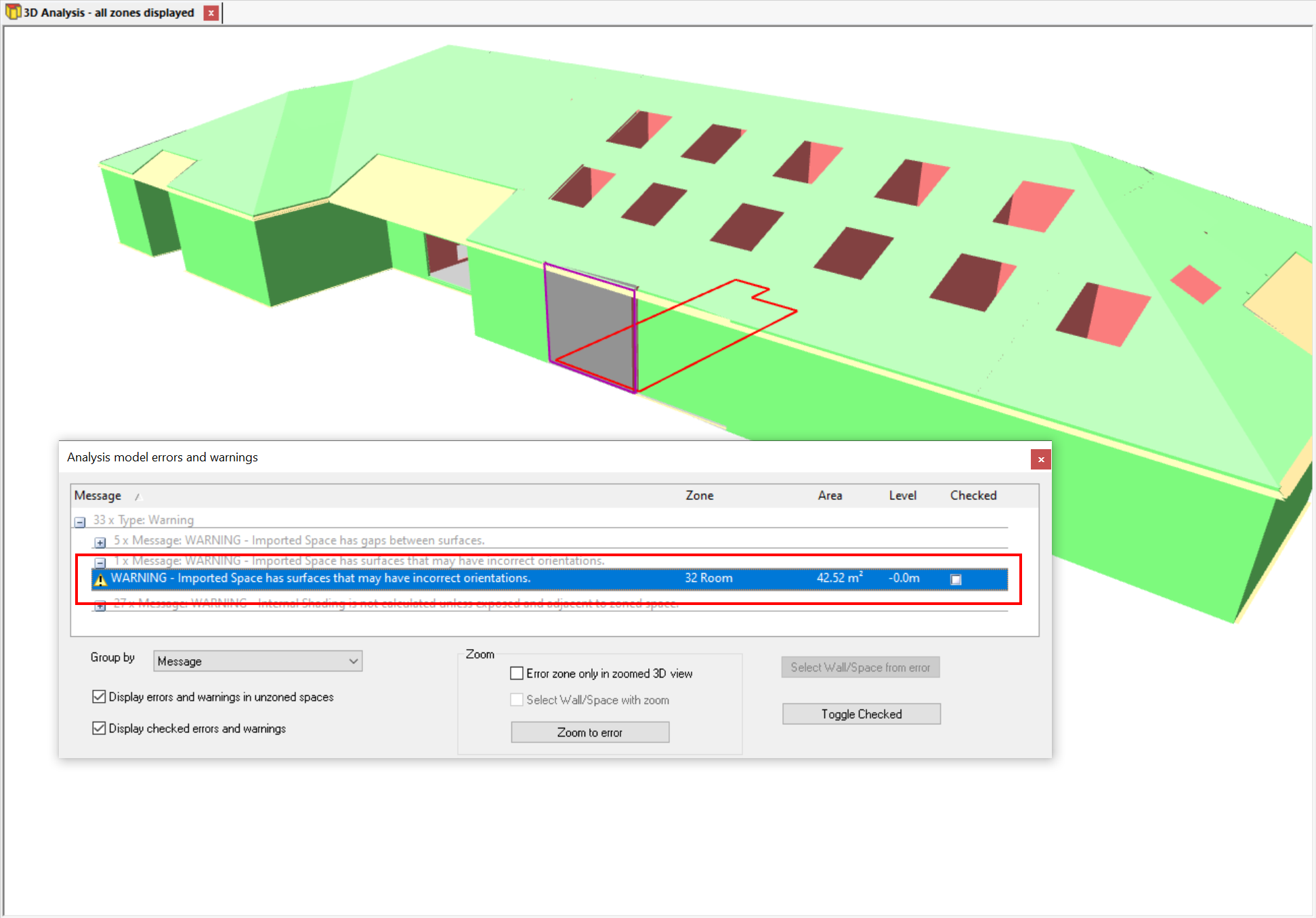
Using the option View >> Display Options >> Analysis will show incorrect surfaces on the boundary of the building coloured grey. Select the surface and the option Reverse Geometry to correct this.
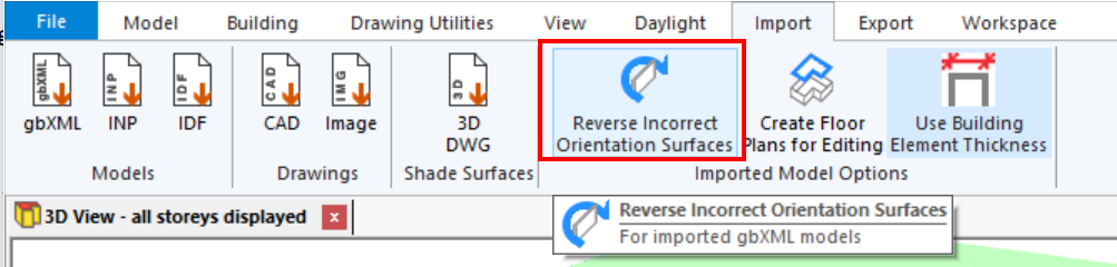
Repair Spaces with Incorrect Orientation Surfaces
If there are many spaces with warnings and therefore many surfaces may need to be corrected, there is an option on the ribbon Reverse Incorrect Orientation Surfaces that can be used instead. This attempts to reverse surfaces as required to repair all such spaces.
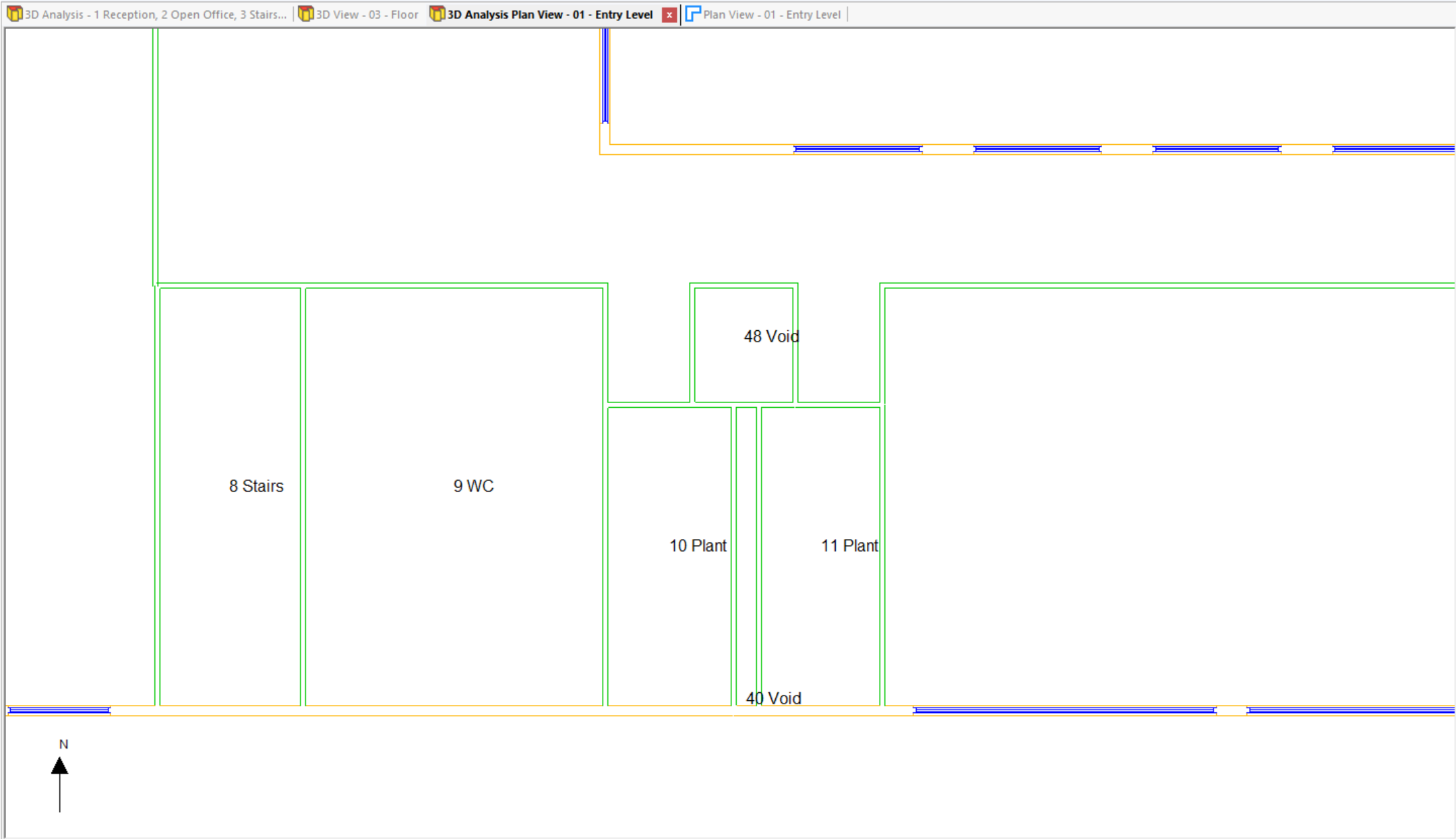
View for Daylight Results
There is an option to create a plan view derived from the analysis model for an imported model on which to display any daylight calculation results. Use Daylight >> New Analysis Plan View.
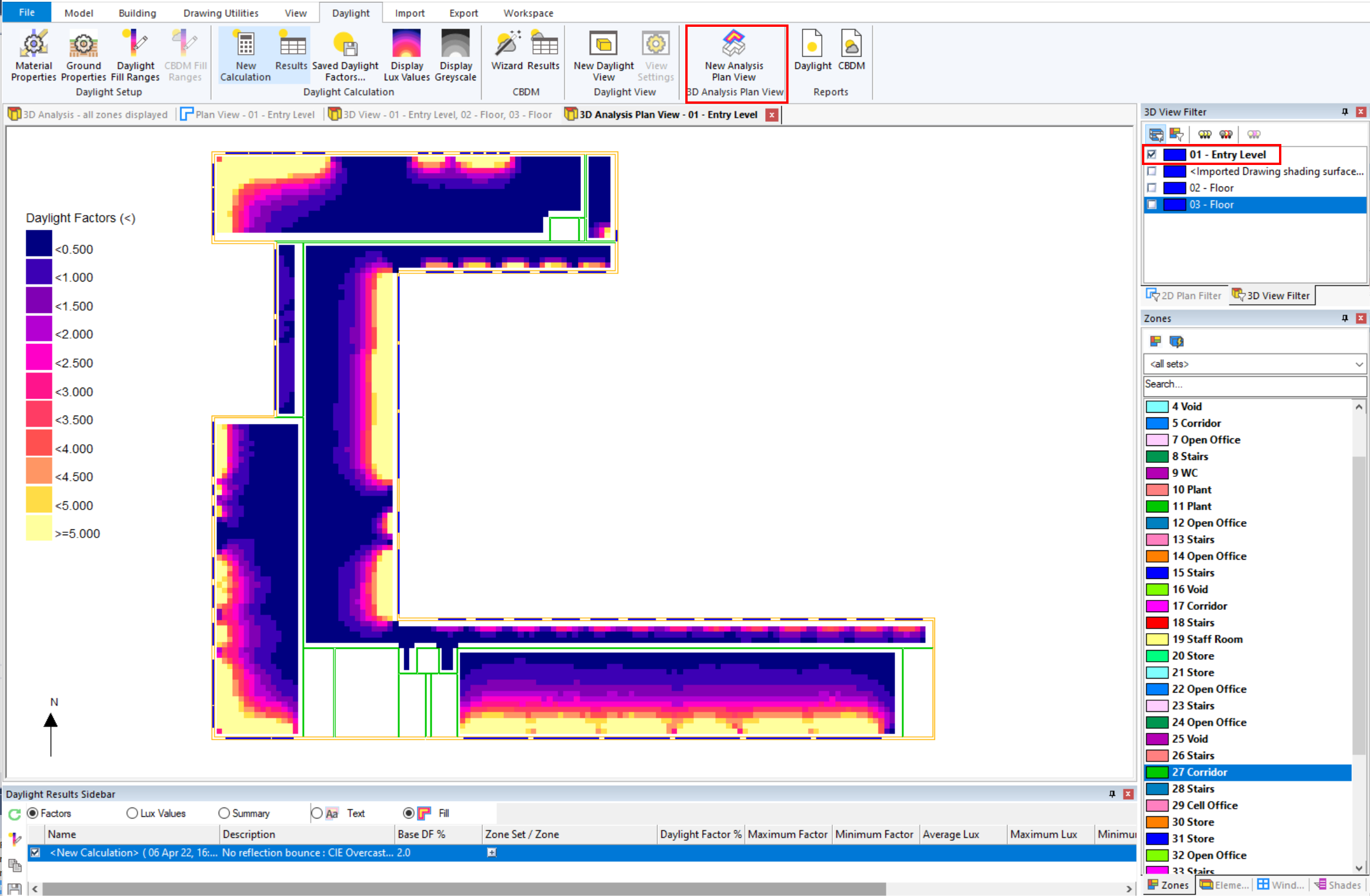
Select the required storey in the 3D View Filter. A plan view of the wall surfaces of spaces associated with the chosen storey(s) is displayed. And the results from the selected calculation for the zones on the storey(s) are shown.
When daylight calculation results are not shown in this view type, zone names are displayed if the option Model >> 2D Zones >> Name is selected.
Creating Floor Plans
You can create 2D floor plans from an imported model to allow the imported spaces to be divided further by adding walls and construction lines. This is particularly useful if you need to add perimeter zoning as required by the EPC conventions.
Note
You can only add internal walls to an editable plan view. For external walls, create a regular storey.
To create a gbXML editable 2D floor plan, go to Import >> Imported Model Options >> Create Floor Plans for Editing in the ribbon:
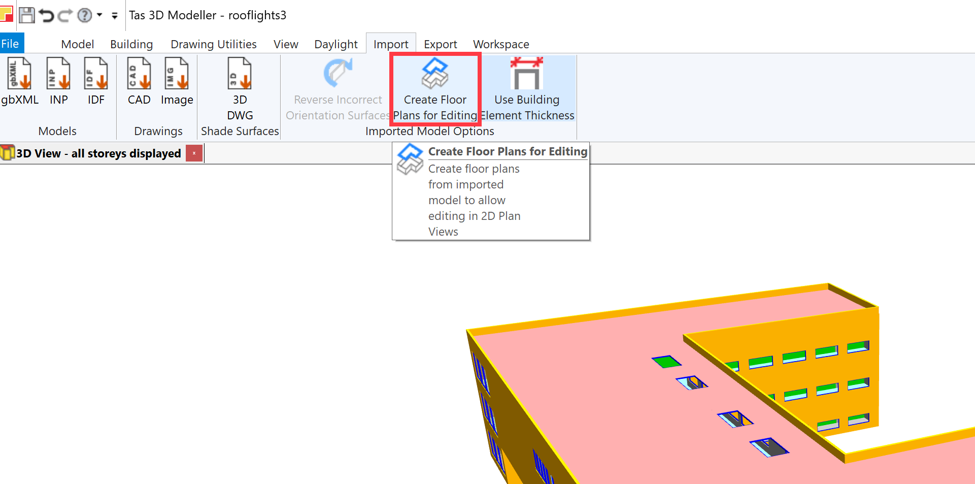
After pressing this button, you can then create 2D views to display the newly created floor plans. Previously, this button was disabled:
Additional zones can be added to an imported gbXML model by sub-dividing an imported space:
Simple internal shades can be placed on these new construction lines and similarly internal windows and doors can be placed on new walls.
Shades
As for standard 3D Tas models, there are three main types of shades that can be added to an imported model:
Simple Shades (e.g. for windows, brise soleils)
Shade Buildings
3D Shade Surfaces (from a 3D DWG)
Simple Shades
Simple shades can be added to the imported gbXML geometry by creating an external zone adjacent to the external fascade using null walls.
Note
Simple external shades cannot be added to editable gbXML floor plans.
After creating a new storey, switch to the 3D view and select a wall (or walls) to which you wish to add external spaces with shades. Right click, and click Copy Null to Storey:
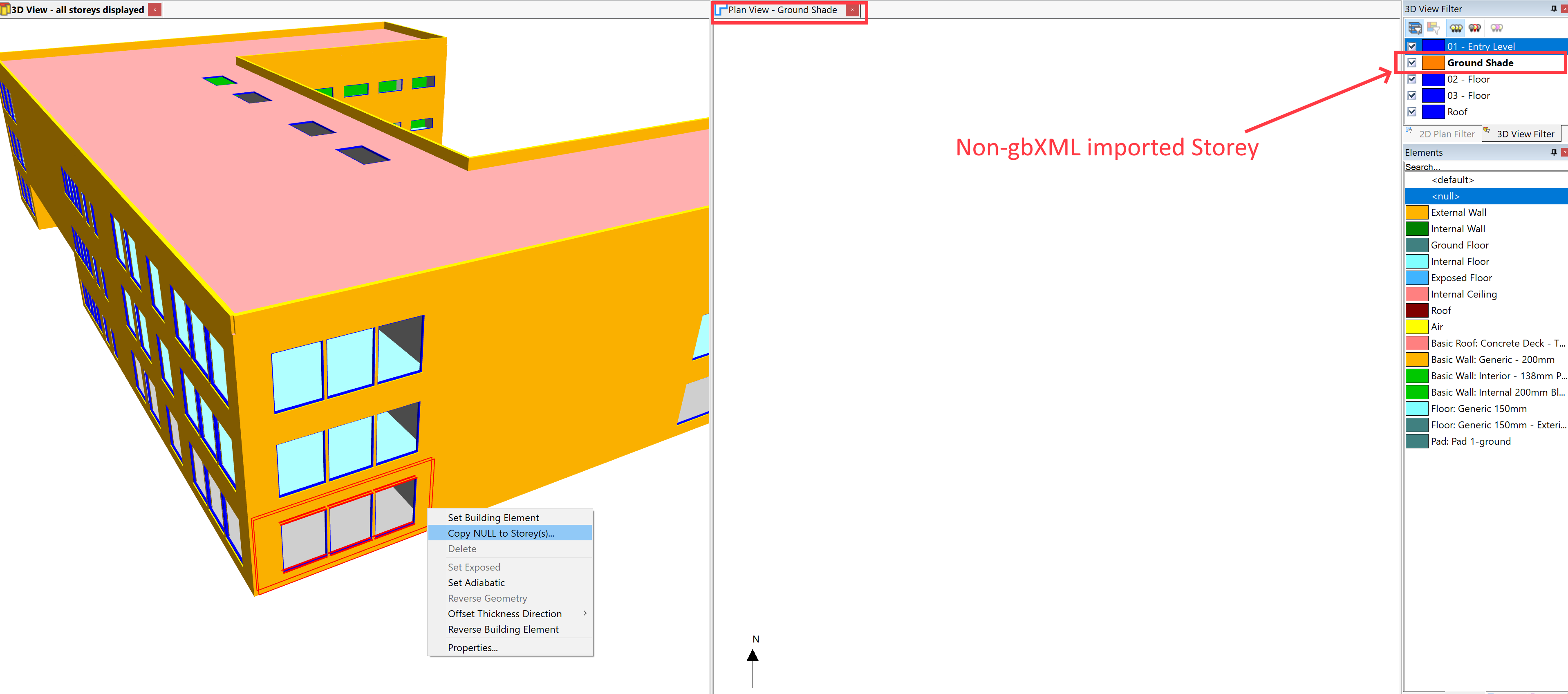
Select a regular storey – that is, a storey that wasn’t created as part of the gbXML import process. This will create a null wall in the 2D plan, which you can add further walls to in order to create an external zone:
Note
You can select walls using the Perimeter option if shades are to be placed on many sides of a building storey. Alternatively there is a Copy Null to Storey option for selected spaces.
You can then zone the space, set the floor and ceiling building elements to null and place a shade:
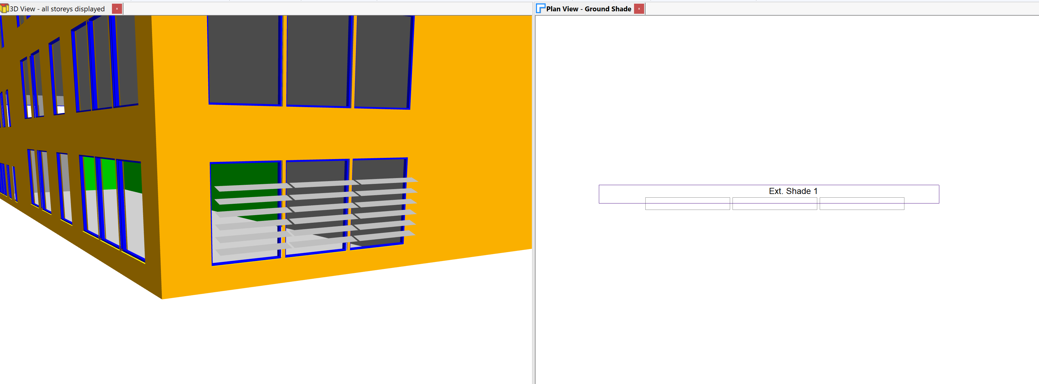
For more information about creating simple shades, see Shades.
Shade Buildings
If you do not have a regular Storey in your Tas3D file, create one.
Shade Buildings can then be added to an imported model in the same way as you would with a standard Tas3D model:

3D Shade Surfaces
A 3D DWG file containing 3D geometry can be imported into both a regular Tas3D model and a model containing imported geometry.
This is useful when modelling complex shading systems that may not be included, for example, in the gbXML export produced by other software.
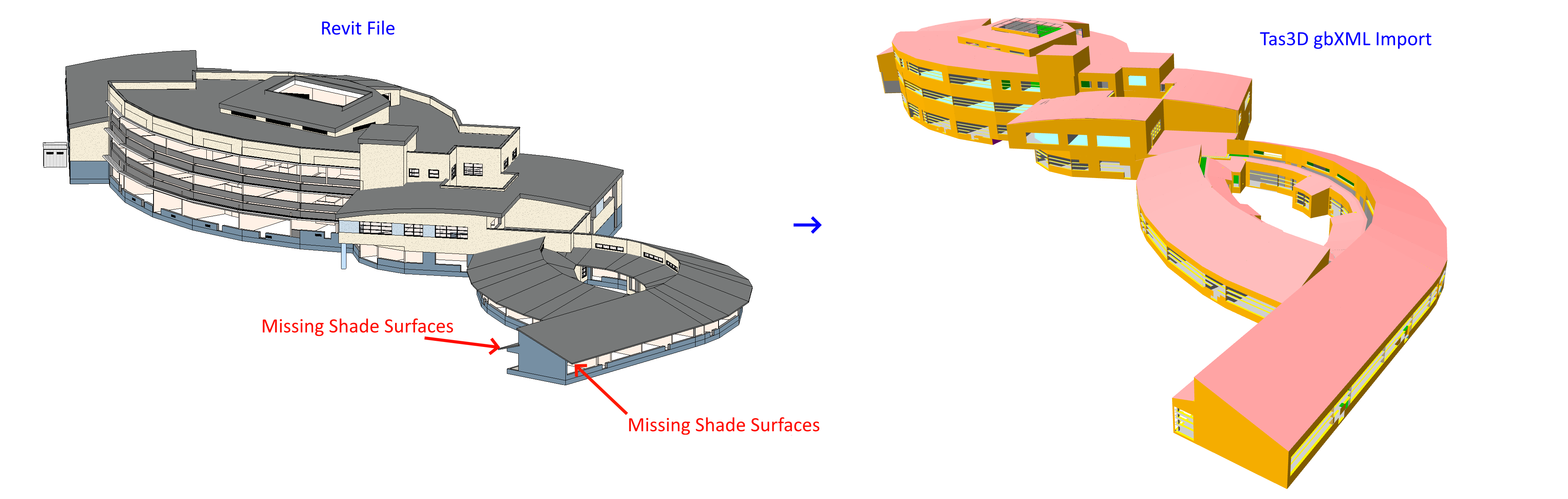
To import the missing shade surfaces in this case, the process is similar to that previously described for standard 3D models. We can use a 3D DWG containing those missing surfaces:
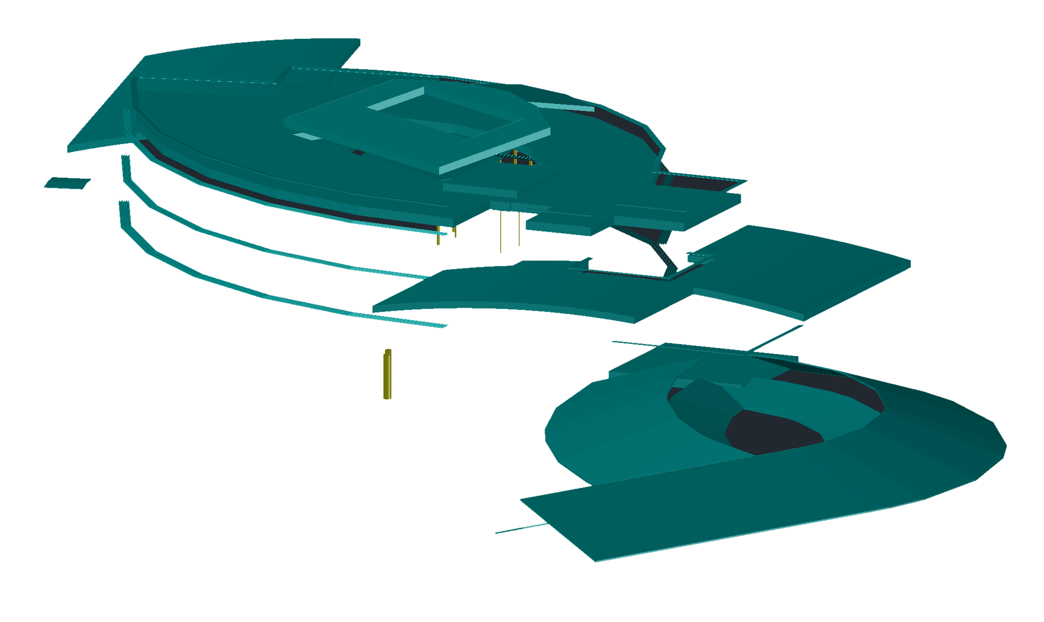
Autocad drawing exported from Revit showing only the missing shade surfaces from the gbXML file.
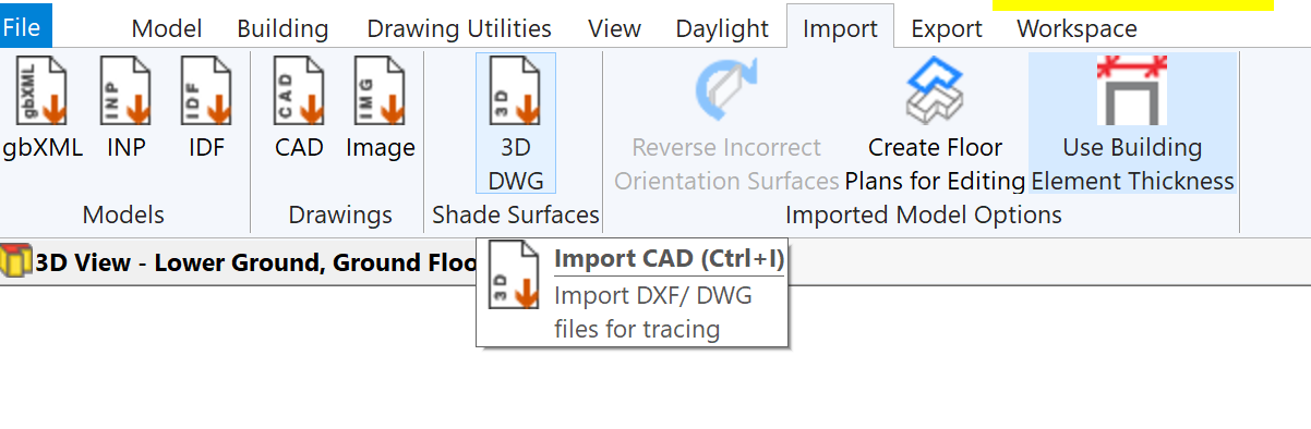
In the 3D modeller, after importing the gbXML file, press the Import DWG button:
Select the 3D DWG and press OK. You will then be presented with a preview of the DWG and some import options. The following example shows shade systems that were not included in the gbXml file.
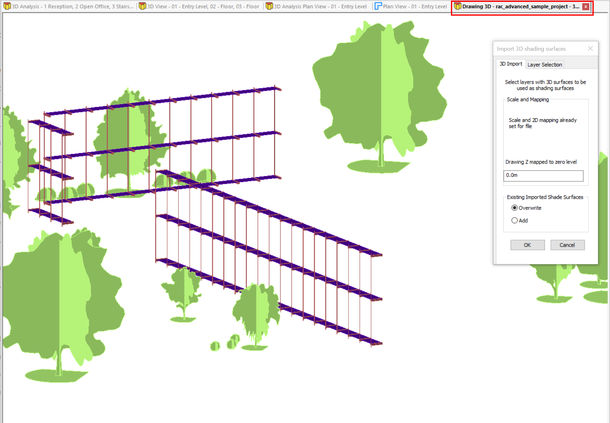
Select the layers you wish to import shade surfaces from on the Layer Selection tab and then switch to the 3D Import tab to complete the process.
Set the height offset (z-mapping), which is used to adjust the height at which the imported geometry is placed, and press OK to complete the process:
The imported shade surfaces appear on their own storey, and can be removed via the Edit Storeys Dialog.
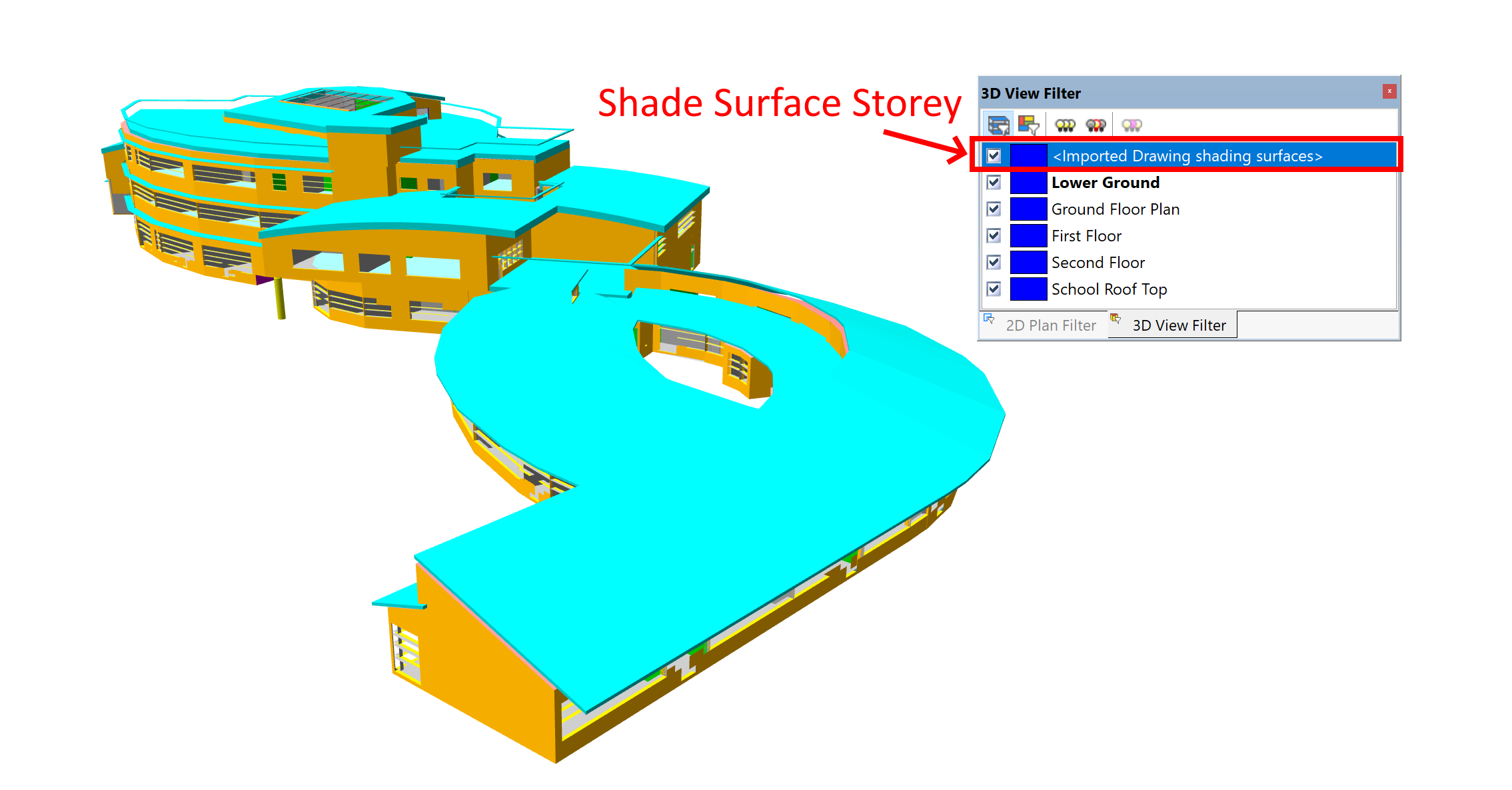
If you import additional shade surfaces from another 3D DWG, you can choose to either merge these with your existing shade surfaces or replace them:
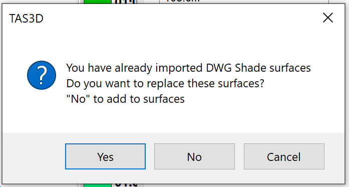
If you merge additional shade surfaces with the existing shade surfaces, they will be placed on the same Storey.