Daylighting
The 3D Modeller has an advanced daylight engine that uses a radiosity based method to calculate the way in which light interacts with the 3D analysis model.
It can be used to calculate:
Lux levels
Vertical Sky Component (VSC)
Rendered daylight views
It is therefore suitable for calculating:
Daylight factors
Uniformity & percentage above base
Climate based daylight modelling
Equivalent first zone (right of light)
Annual Probable Sunlight Hours
Permanent Overshadowing
Daylight Distribution
Simple daylight calculations such as lux levels and daylight factors are calculated directly in the 3D modeller.
Metrics which rely on performing a number of daylight calculations and collating the results are performed via Tas Utilities such as the Climate Based Daylight Modelling Wizard.
Note
Before performing daylight calculations, you should set up the material reflectances & transmittances and refresh your analysis model.
Material Properties
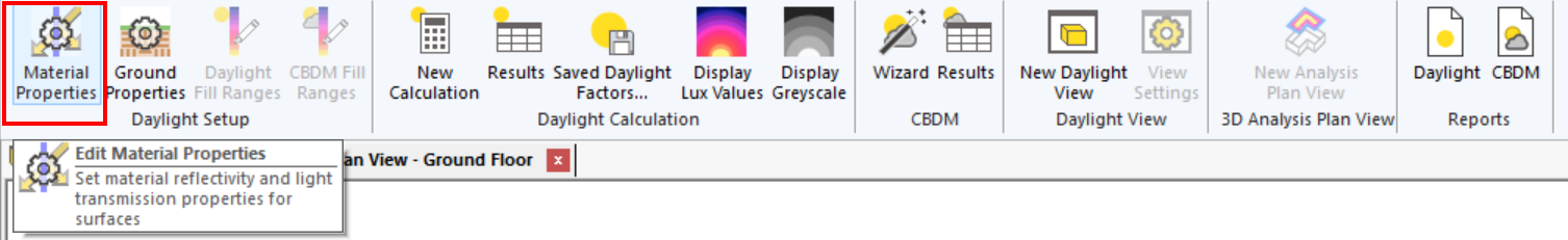
To adjust the reflectances and transmittances of entities in the 3D modeller, go to Daylight >> Daylight Setup >> Material Properties in the ribbon:
The dialog that opens allows you to set-up the reflectances and transmittances for:
Building Element Types
Building Elements
Windows
Shades
Note
Only transparent elements can have a transmission.
Building Element Types
Building Elements in the 3D modeller can have a type as explained in Building Element Types.
You can change the reflectance and transmission of one of the pre-defined building element types here:
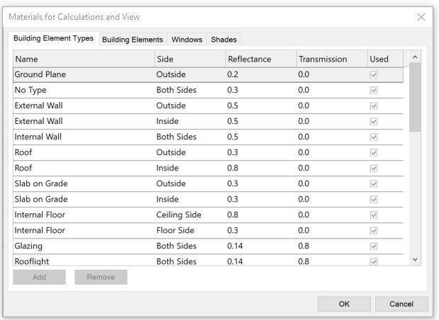
Note
The sum of the reflectance and transmittance should not be greater than 1, but can be less than 1.
If it is less than 1, the unaccounted-for light is assumed to be absorbed.
Building Elements
If you wish to set the reflectance/transmittance of a particular Building Element, you can do so via the Building Elements tab:
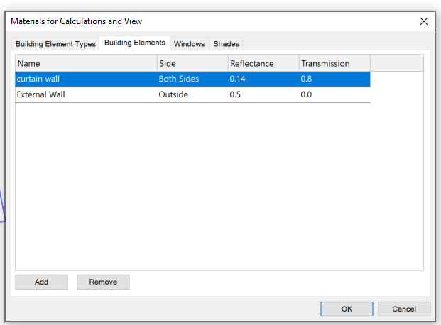
Adding a Building Element here will override the reflectance/transmittance set in the Building Element Types tab.
Windows
The reflectances & transmittances of windows can be set in the Windows tab:
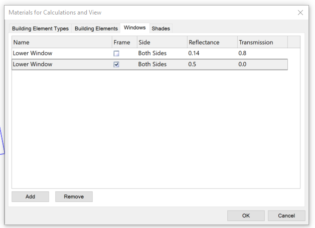
You can also set the Frame properties by checking the Frame checkbox. If you wish to set both the properties of the pane and the frame, you’ll need to add two entries as per the above.
Shades
Shade properties are set in exactly the same way as window properties. Setting properties for an individual shade will override any settings in the Building Element Type tab.
Side
The side property can take several values depending on the type of entity it is being applied to:
Both Sides
Floor Side
Ceiling Side
Inside
Outside
The Both Sides option is useful when both the inside and outside surface of an element reflect light in the same way:
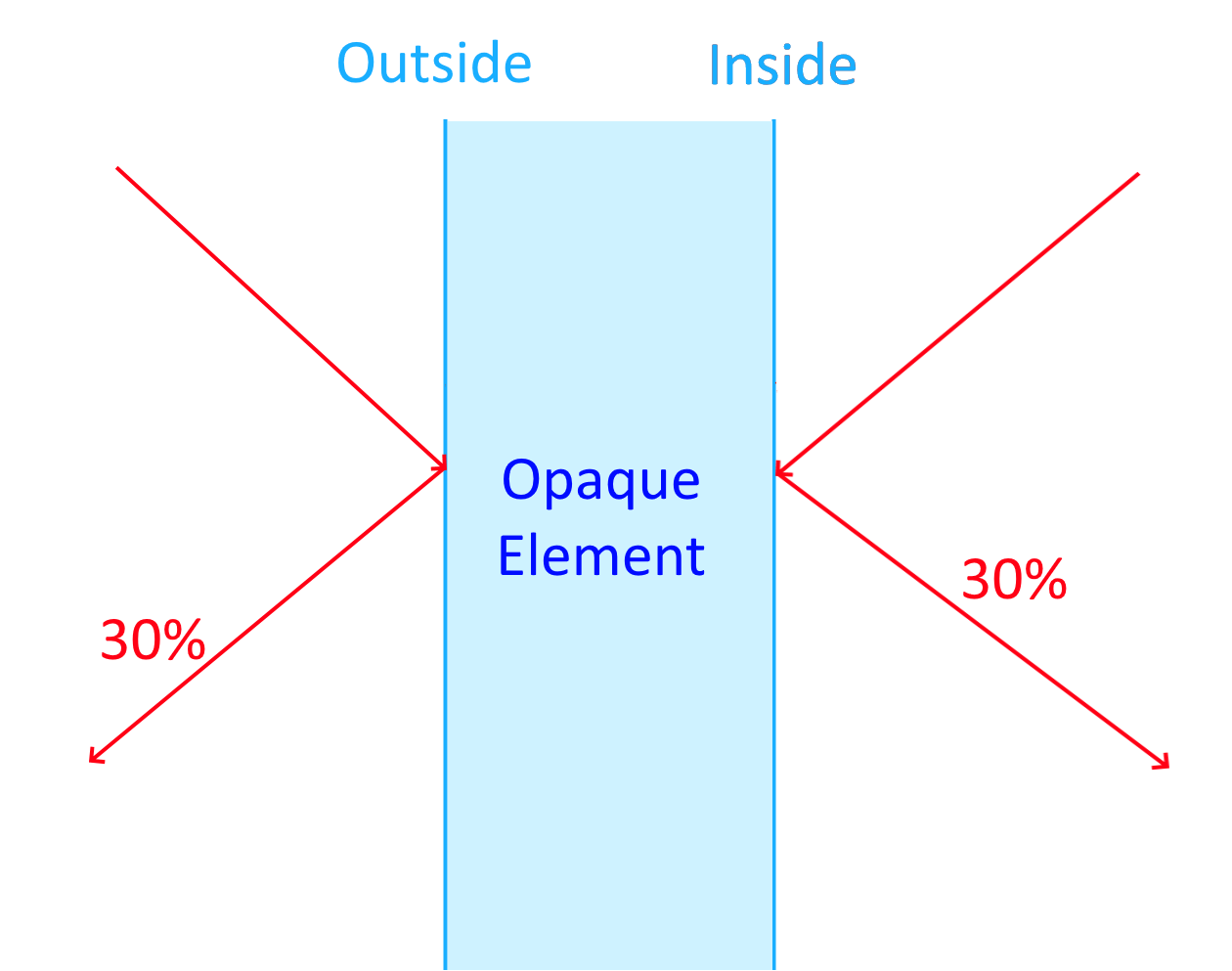
If the inside reflects differently to the outside surface, you should set the reflections of these surfaces separately.
When two building elements merge (e.g. an internal floor merging with an internal ceiling), the building element type of the merged construction is always Internal Floor:
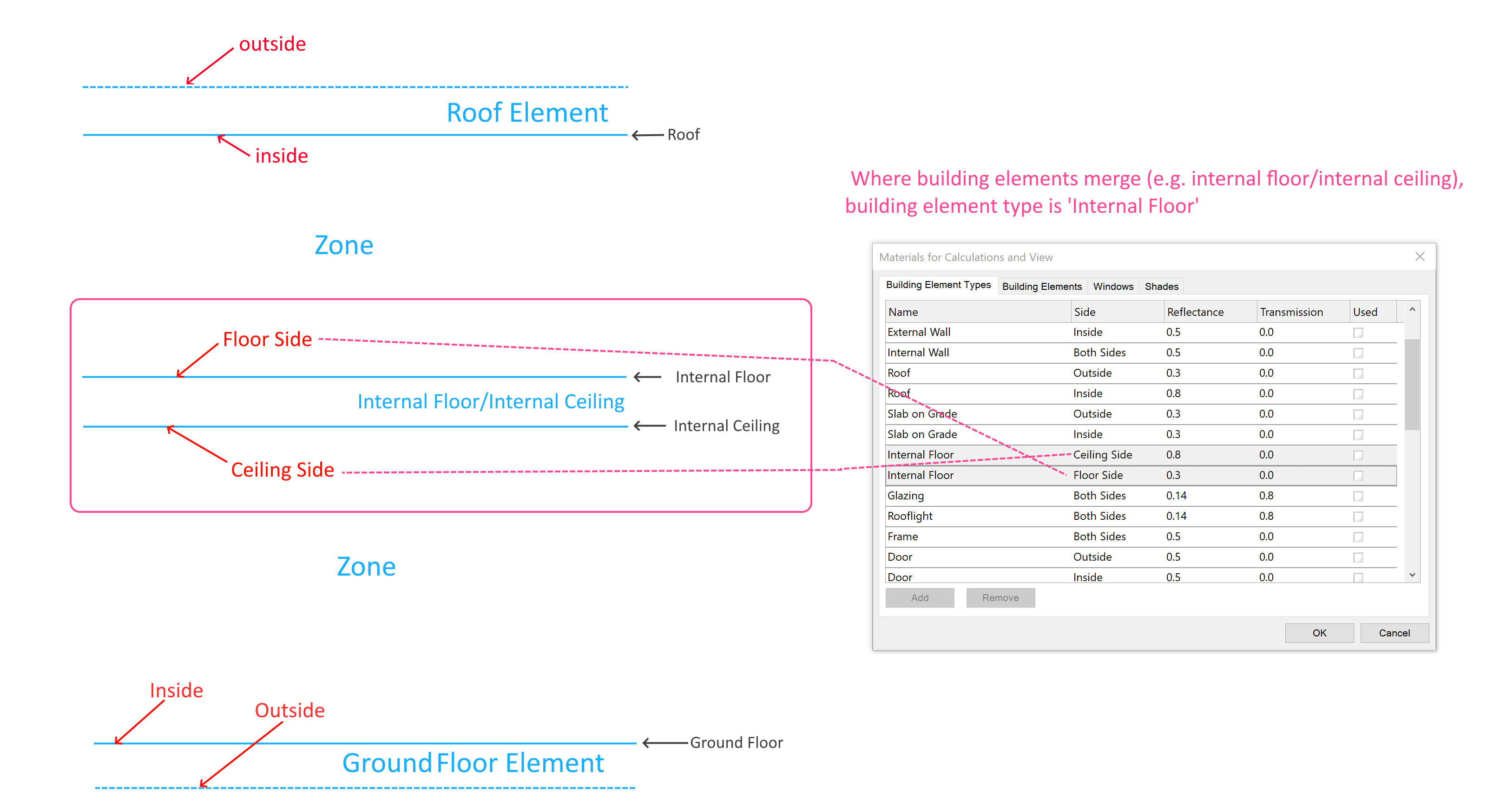
The default Ground building element has the Slab On Grade type.
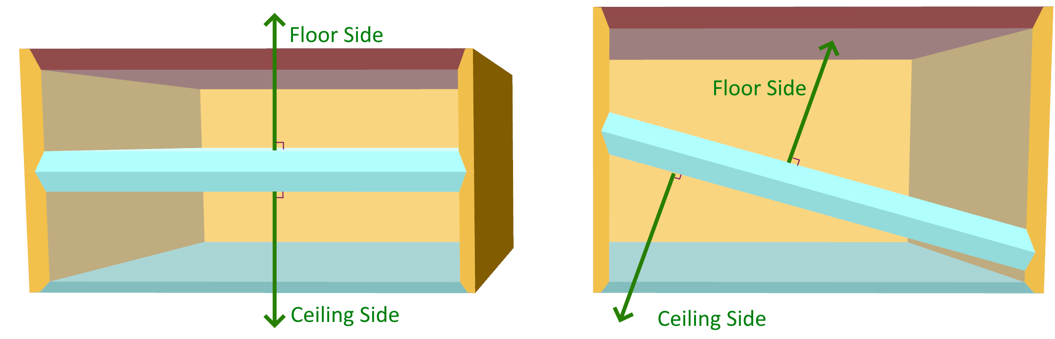
The floor side of a surface always has a normal (a perpendicular line) pointing upwards:
Ground Properties
By default, the daylight engine models the ground plane to be at 0m.
You can change the height of the ground plane by clicking on Daylight >> Daylight Setup >> Ground Properties in the ribbon:
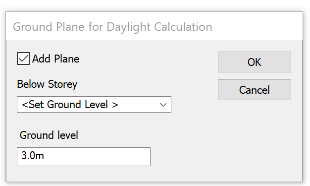
If you uncheck the Add Plane box, no ground is modelled. This can be useful if you have drawn in the ground yourself, or have imported 3D DWG shade surfaces.
If you select Set Ground Level in the Below Storey box, you can enter the position of the ground directly.
You can also select one of your existing Storeys and use its Level as the ground level.
Basic Daylight Calculations
To calculate basic daylight metrics such as Daylight Factor in the 3D modeller, create your Analysis Model and Refresh it if it is not up to date. For details, see Analysis Model.
Then, click on Analyse >> Daylight Calculations >> New Calculation in the ribbon:
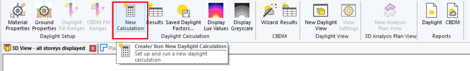
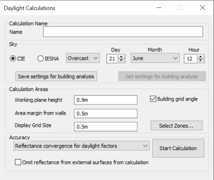
The daylight calculations dialog will open:
In order to produce accurate images, you should set the material properties of the entities in the model. For more information, see Material Properties.
You should also ensure the building location is correct, by adjusting the longitude, latitude and timezone as specified in Building Properties.
Sky
The sky section of the dialog allows you to set the Date and Time the calculation will be performed, and the model that will be used for the sky.
The CIE skies are described in ISO 15469 and are predominantly used in the UK and Europe.
The IESNA sky is defined by the Illuminating Engineering Society of North America and is primarily used for ASHRAE.
For each of these sky models, you can specify if the sky should be:
Overcast
Clear
Intermediate
Uniform
The CIE sky types roughly resemble the below:
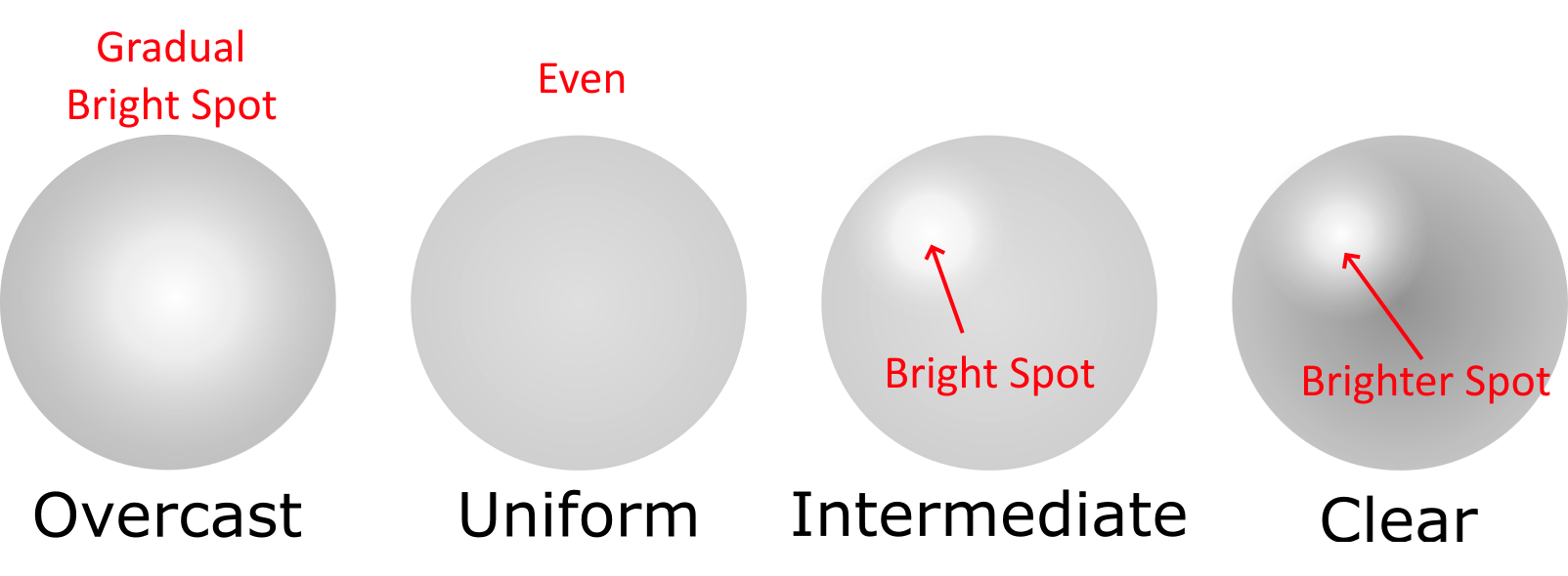
The overcast sky varies gradually with the brightest part directly above the model. The Clear sky has a bright spot where the sun is, and the intermediate sky is similar. The uniform sky has a single illuminance.
The Save/Get Settings for Building Analysis buttons save your current settings in case you wish to use these settings again in the future.
Calculation Areas
The Calculation Areas box allows you to control the plane on which results are calculated.
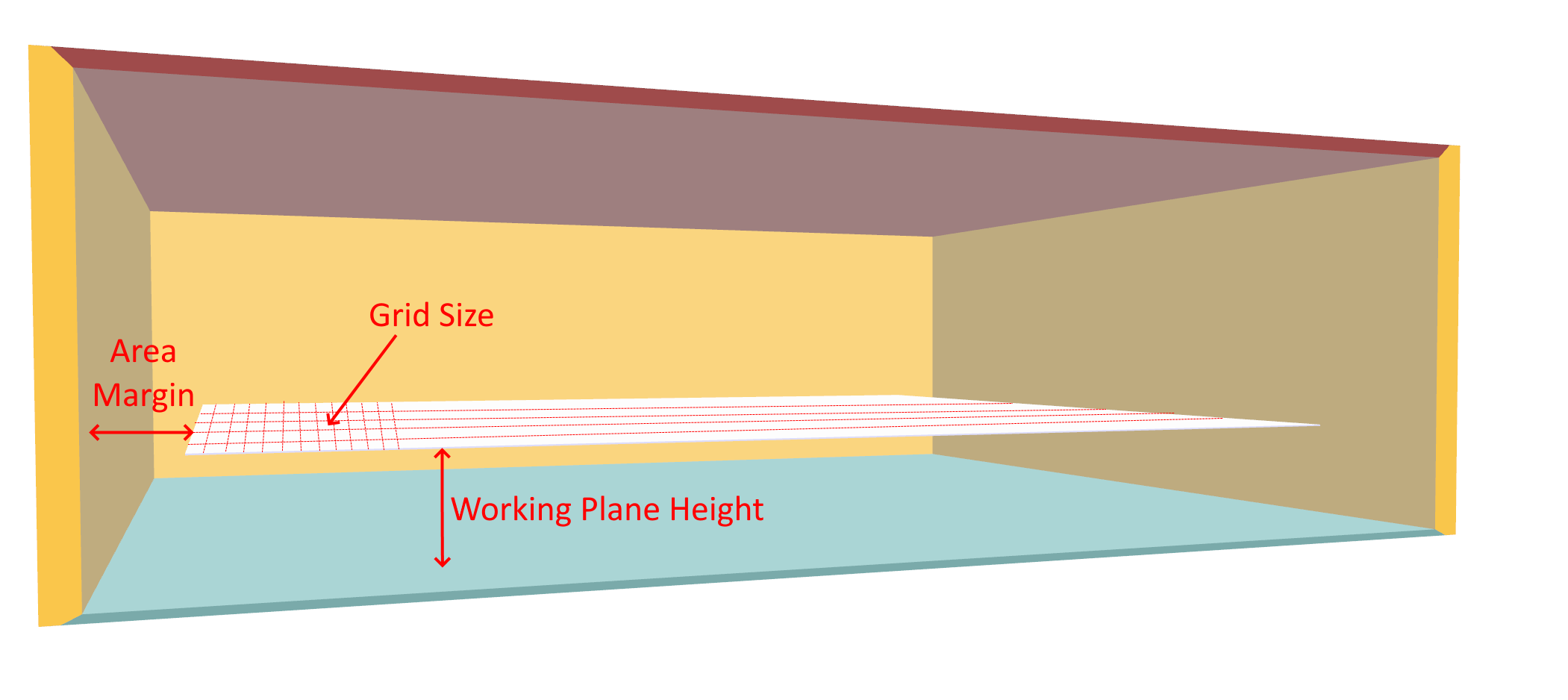
The Area Margin from Wall field determines the gap that should be excluded between the wall and the area you are interested in analysing.
The Working Plane Height specifies the height of the plane you wish to analyse.
The Grid Size determines the spacing between the points on the grid; the smaller the grid size, the more points will be analysed and the slower the calculation will be.
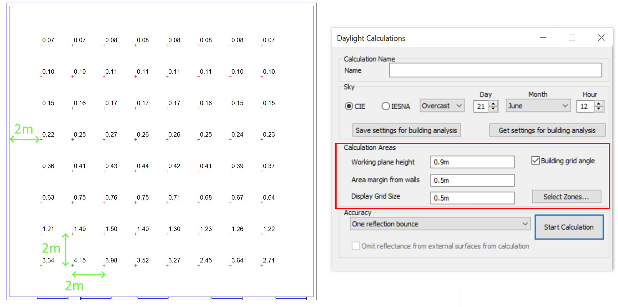
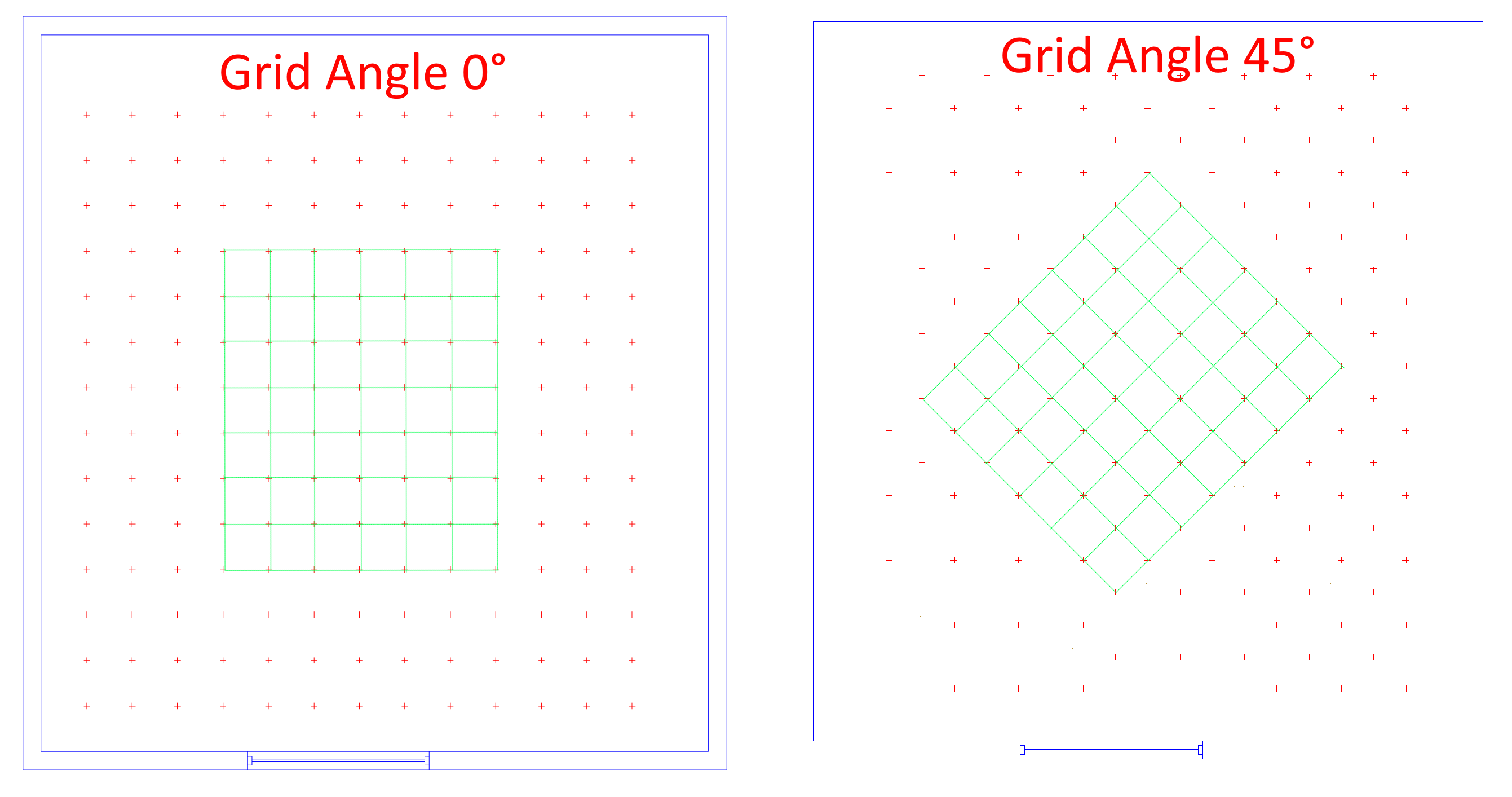
The Building Grid Angle checkbox determines whether the angle of the analysis grid matches the building grid angle set in the model section of the ribbon:
The Select Zones button allows you to select which zones will be analysed as part of that calculation. By default, all spaces which have access to daylight are included. New spaces may have to be manually included in subsequent calculations if the model is edited and a new analysis model is created. Zones that do not have access to daylight cannot be included in the daylight calculations.
Accuracy
The Accuracy options in the 3D modeller generally relate to the level of convergence during the calculation.
During a daylight calculation, calculations are performed for each surface in the model to determine how much of every other another surface is directly visible from that surface. These are known as view coefficients.
The view coefficients are then used to calculate how much light would be visible from every surface as light bounces around the space. By tracking more and more bounces of the light, eventually the illuminances will converge (stop changing). The higher the level of convergence (the more bounces there are), the more accurate the result but the longer the calculation will take.
The options in the 3D modeller are:
No Bounce (direct light only from the sky and sun)
One Bounce
Reflectance convergence for preview (70% convergence)
Reflectance convergence for Daylight Factors (95% convergence)
Reflectance convergence for detailed analysis (99% convergence)
The Omit reflectance from external surfaces for calculation checkbox excludes reflections from external geometry such as surrounding shade buildings, or reflections from the outside of the building itself. It does not omit reflections from the ground outside.
In the dropdown, there is also the option to perform Vertical Sky Component calculations which are window-based calculations. It is performed for the centre point of a window, and is the ratio of the amount of light hitting that point to the amount that could hit an unobstructed horizontal plane.
Viewing Results
The results of daylight calculations can be viewed as a text summary, on a 2D floor plan or in various reports.
Summary
When a daylight calculation finishes, a summary of the results appears in the sidebar at the bottom of the screen:
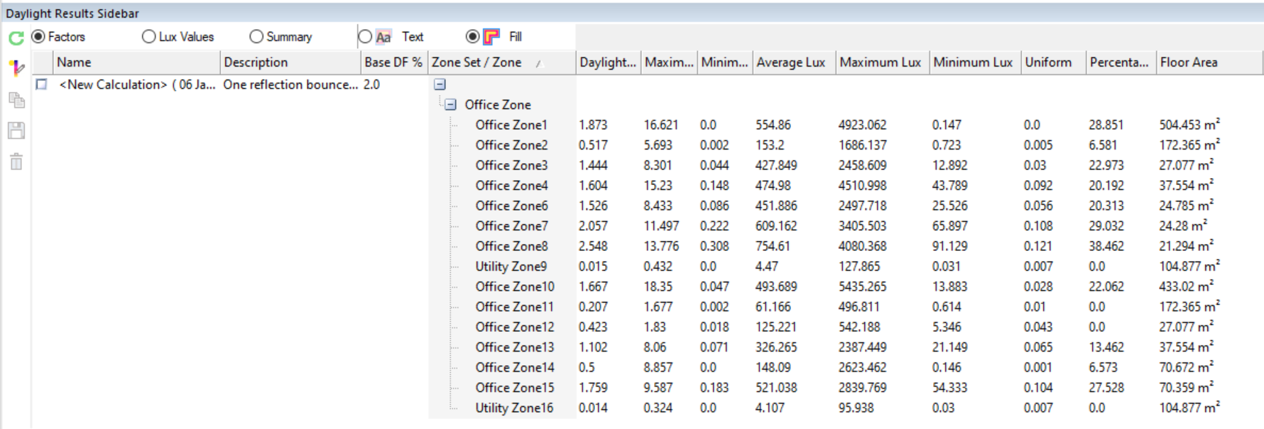
The Daylight Factor% column represents the average daylight factor for the space.
The illuminance of the space is also given in Lux.
The Uniformity is given by the minimum illuminance divided by the average illuminance. This is a measure of how evenly distributed the light is in the space:
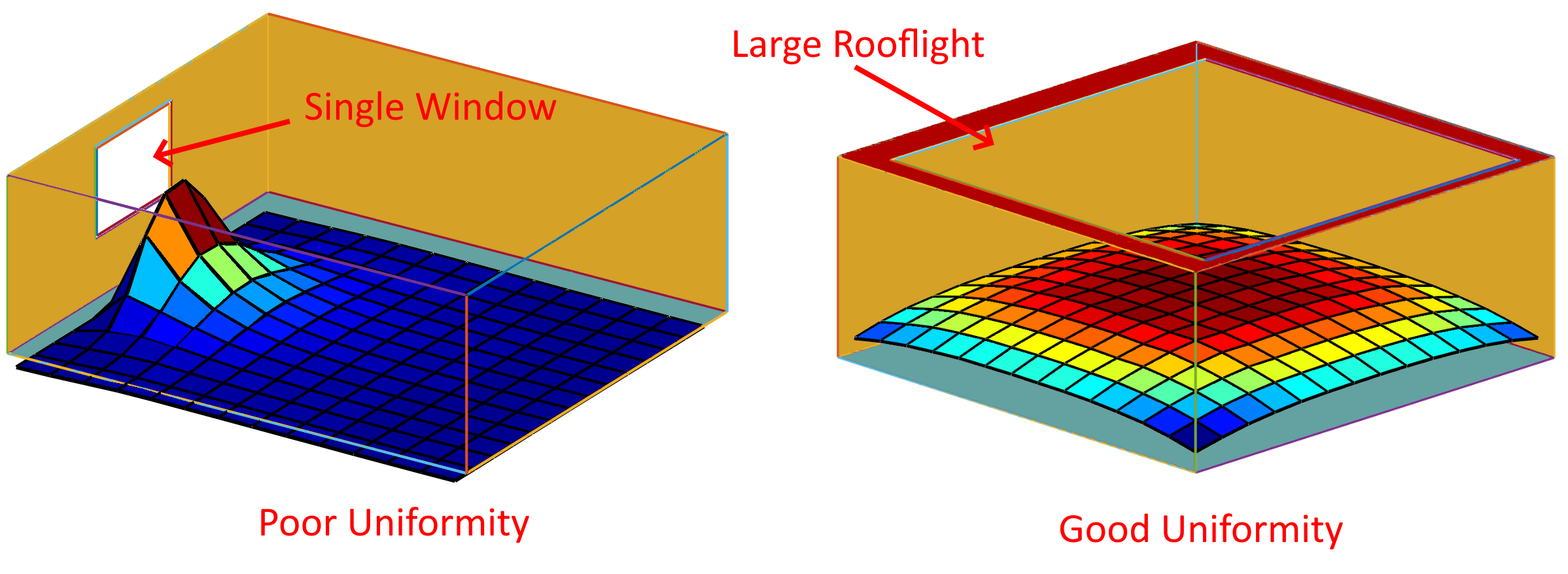
The space on the left has a single window so the light is much stronger near one facade. The uniformity is low. The space on the right has a single large rooflight; the brightness is similar throughout the space, so the uniformity is close to 1.
The Percentage Above Base column refers to the amount of space, expressed as a percentage, that has a daylight factor above the value specified in the Base DF % column:
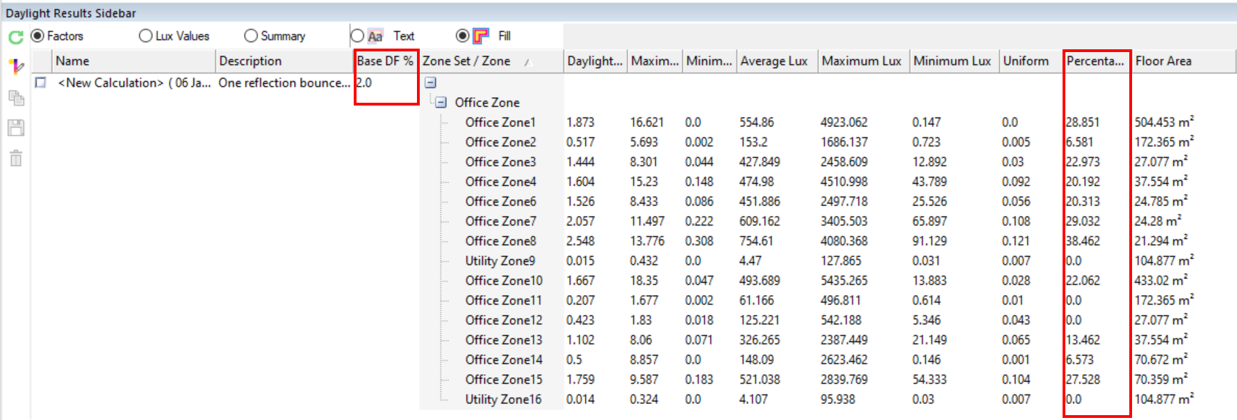
This is useful if you have a minimum daylight factor you are trying to achieve, and you wish to see how much of a zone reaches that minimum.
The Floor Area column specifies the floor area of the zone being analysed, and is not affected by the area margin from wall used during the calculation.
2D Plan View
The results of a daylight calculation can be viewed on a 2D plan view.
Select the calculation in the Results Sidebar and use the radio buttons to control the type of display. The results will be displayed on the current 2D Plan view.
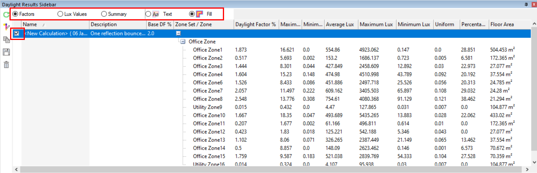
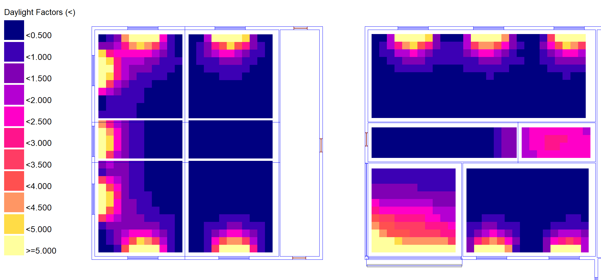
Selecting Fill and Factors or Lux Values results in a coloured representation of the results:
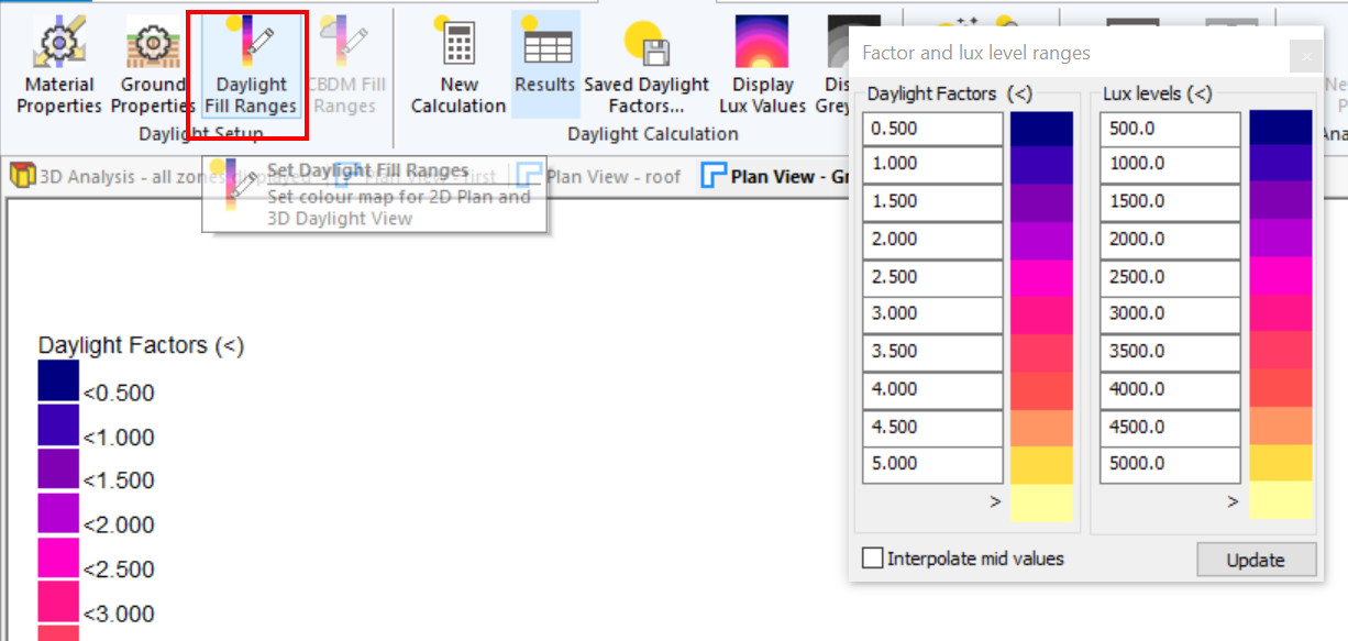
The colours used for each band of lux values or daylight factors can be changed by selecting Daylight Fill Ranges on the ribbon:
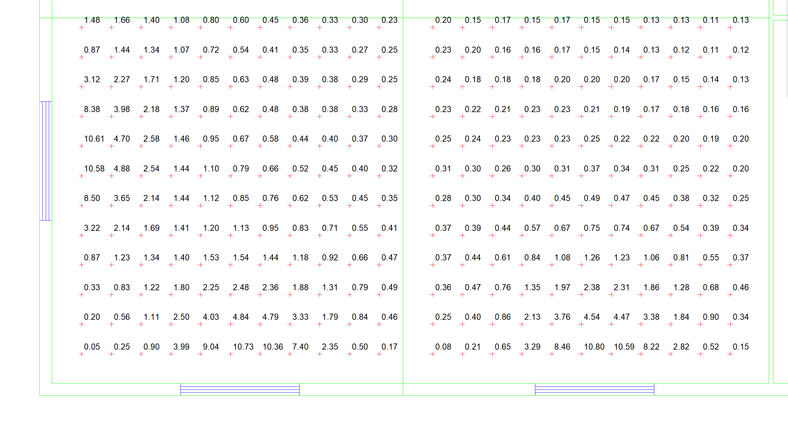
Setting Text instead of Fill and selecting Daylight Factors or Lux Values results in the text values being plotted on the zone plan view:
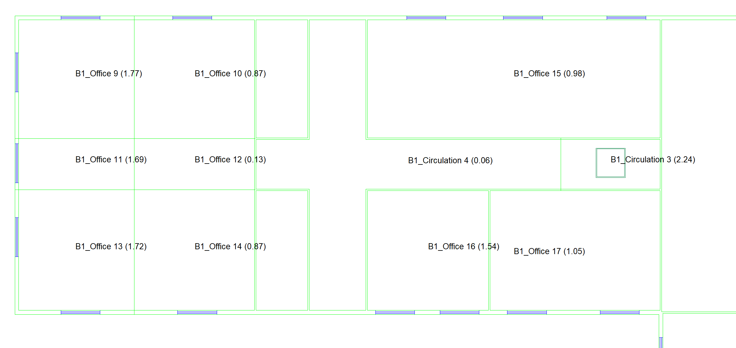
The Summary option displays the zone name and daylight factor on each zone in the plan view:
Reports
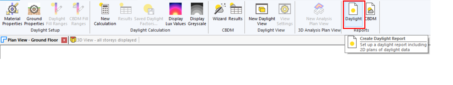
A report can be generated summarising the results of a basic daylight calculation by going to Daylight >> Reports >> Daylight in the ribbon:
The daylight report contains zone diagrams with the results coloured, and summarises the results along with the reflectances and transmittances that are currently set in the model.
Rendered Daylight views
You can generate an accurate image of how a building will be illuminated with natural light using rendered daylight views. These are particularly useful when performing advanced interior shadow casting. The radiosity daylight engine may be used to model light interacting with the building geometry.
This image is a Reflected light view with a clear sky.
You can also generate a Simple shadows view as an alternative to displaying shadows in a 3D Analysis view. This is recommended in particular for interior shadow studies.
You may also view the resulting lux values from a new daylight calculation. The lux values on the surfaces are determined by the reflected light solution used in the calculation.
Prerequisites
To produce accurate images, you should set the material properties of the entities in the model. For more information, see Material Properties.
You should also ensure the building location is correct, by adjusting the longitude, latitude and timezone as specified in Building Properties.
Generating
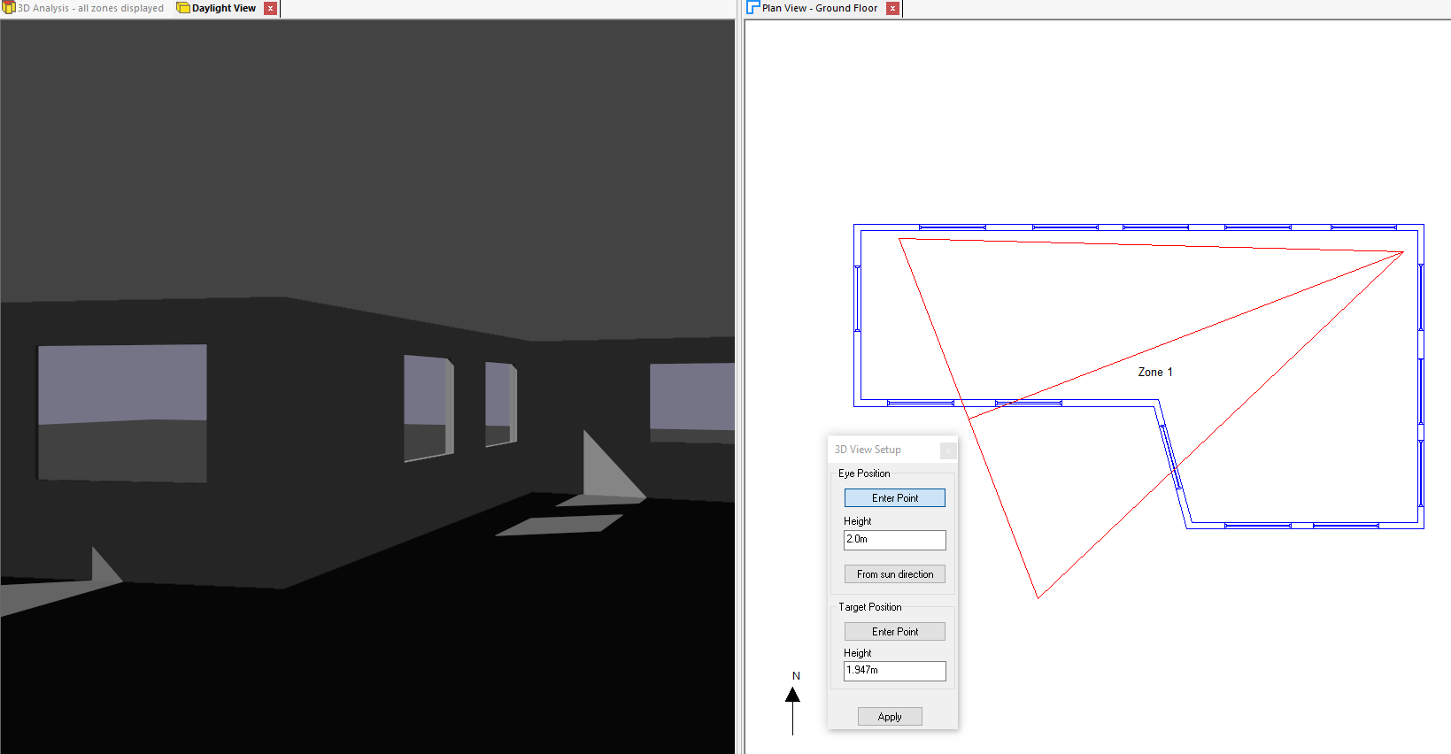
To generate a rendered daylight view, use an existing 3D view to set the viewpoint you wish to render the scene from.
Then press Daylight >> Daylight View >> New Daylight View from ribbon. A new daylight view will open with the same viewpoint as the current 3D view:
You can also use the Camera Setup tool with the daylight view.
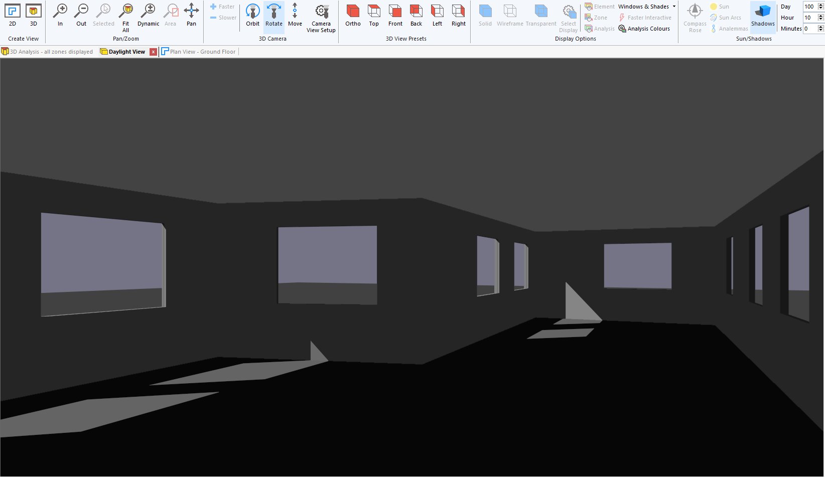
By default, this view shows simple shadows. You can set the day and time for which the shadows are displayed using the same options as for an analysis model 3D view.

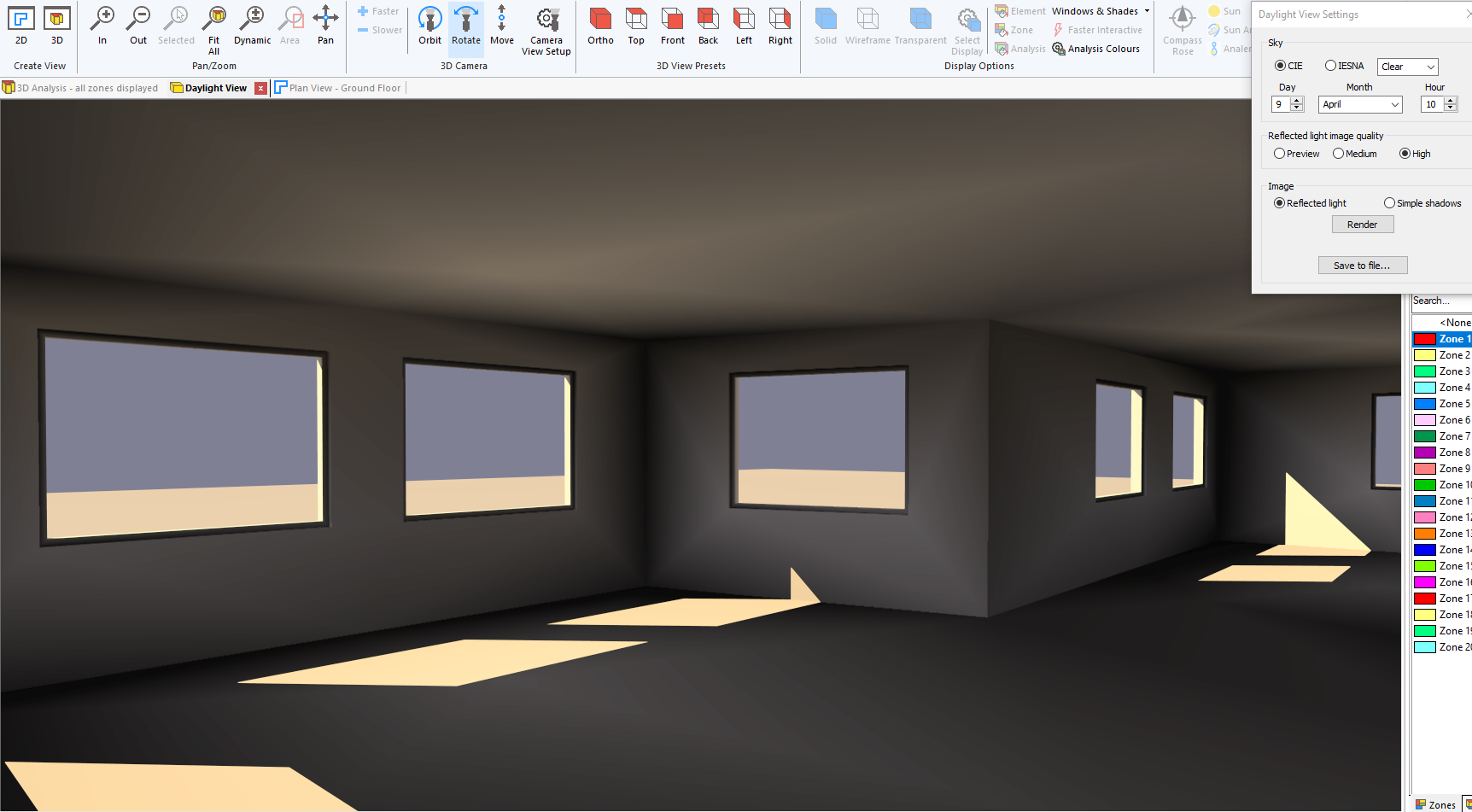
Alternatively set via Analyse >> Daylight Views >> Settings in the ribbon:
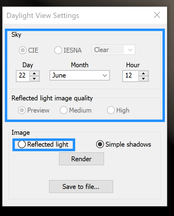
By selecting Reflected Light, the Sky type settings will become enabled. These settings match those in the Daylight Calculation dialog; for more information, see Sky.
Press Render to generate the scene. The Reflected light image quality sets the mesh size and convergence of the radiosity calculation.
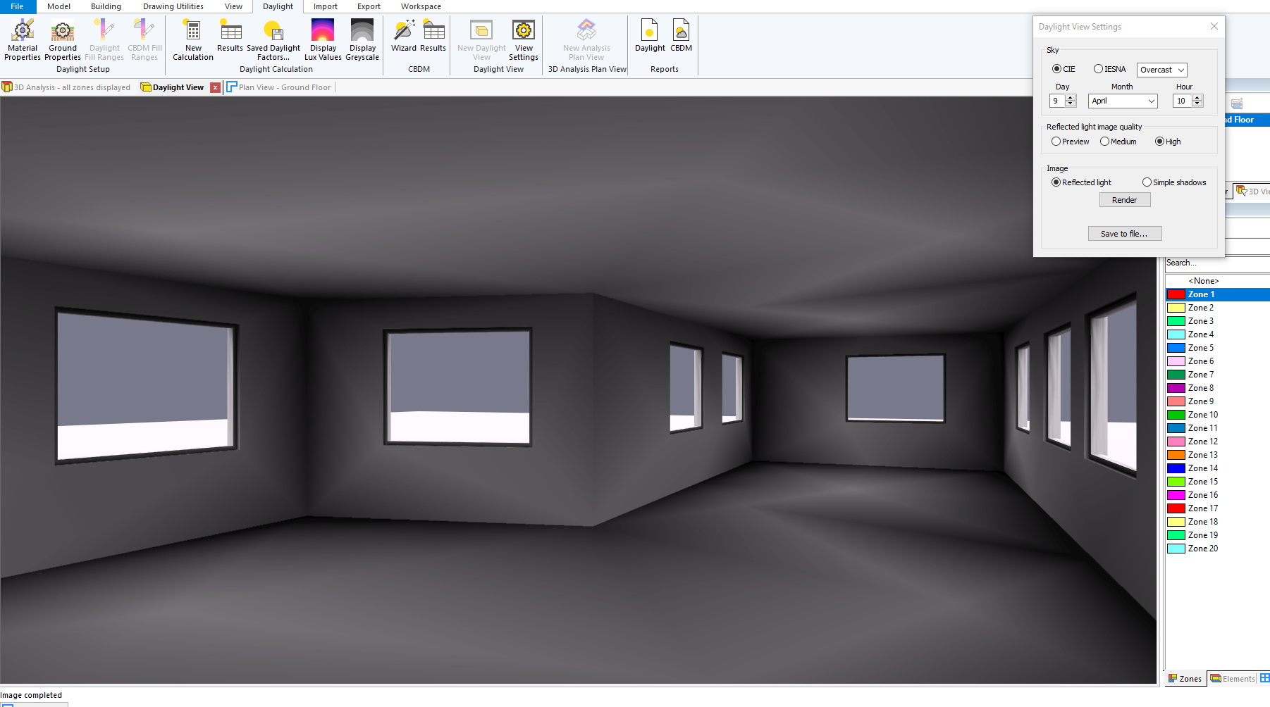
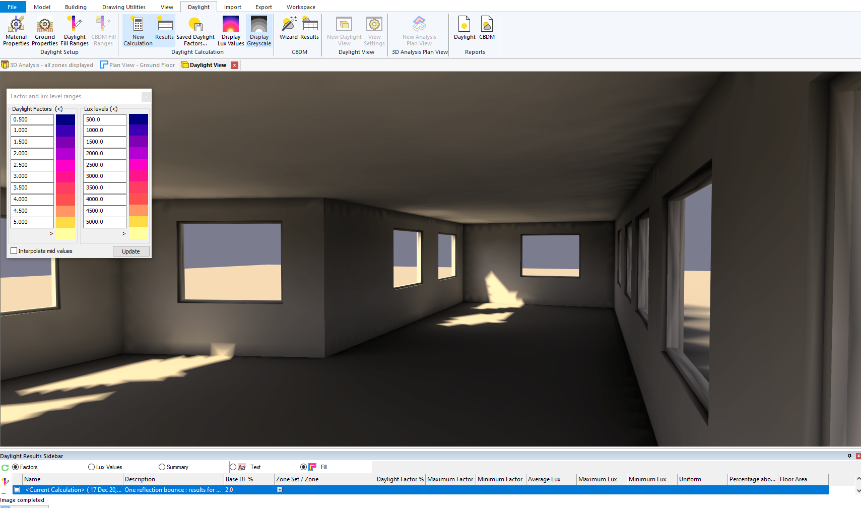
This shows a reflected light view for an overcast sky.
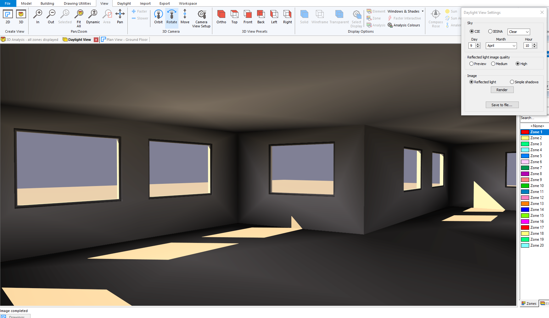
And for a clear sky.
Using View ribbon options such as Orbit, Rotate, Move or Pan to manipulate the view enters an interactive view mode. Transparent windows are drawn with a mesh and no shadows are drawn.
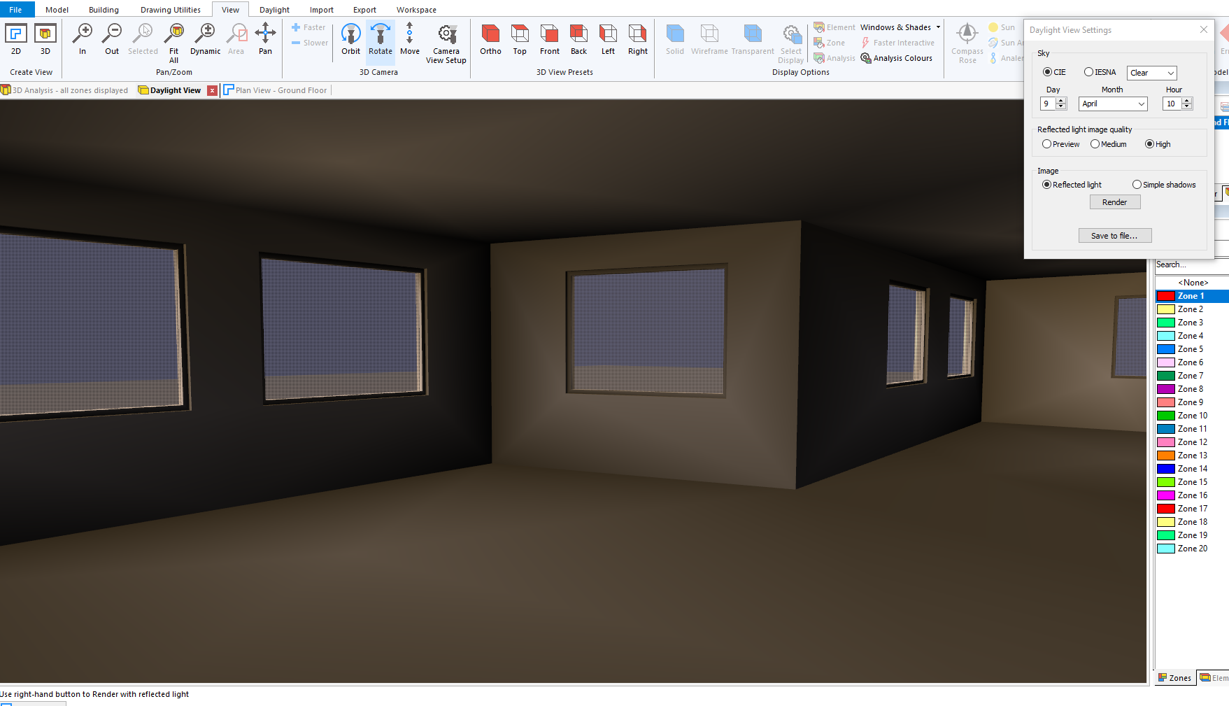
To regenerate an image with shadows, use the right hand button or the Render button on the Settings dialog.
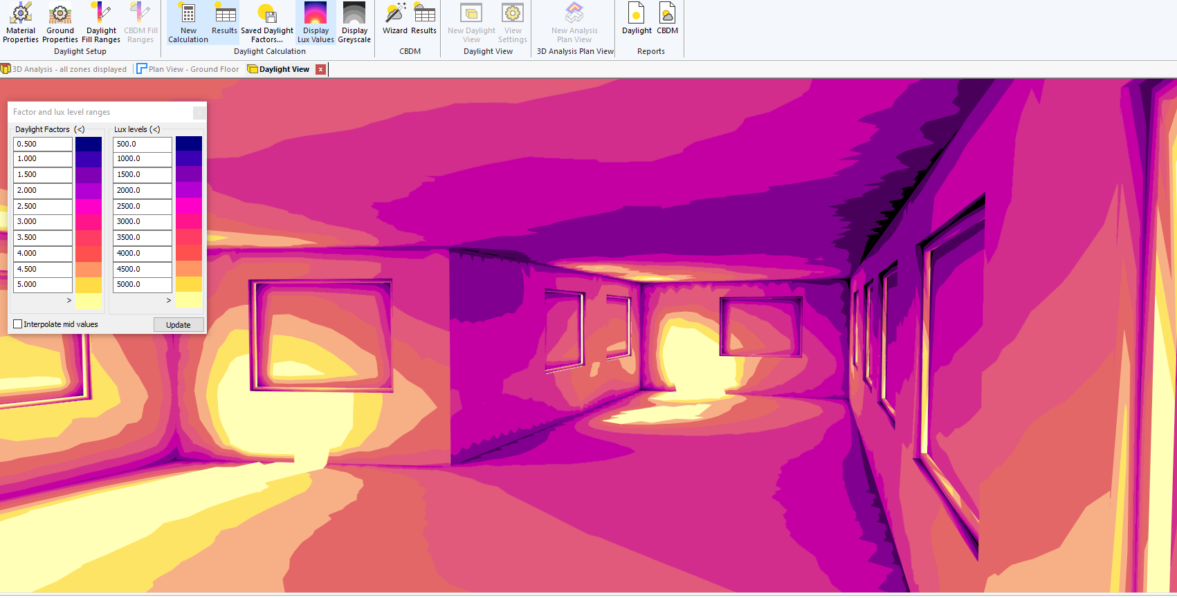
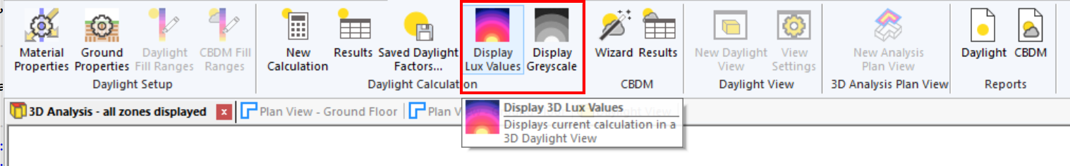
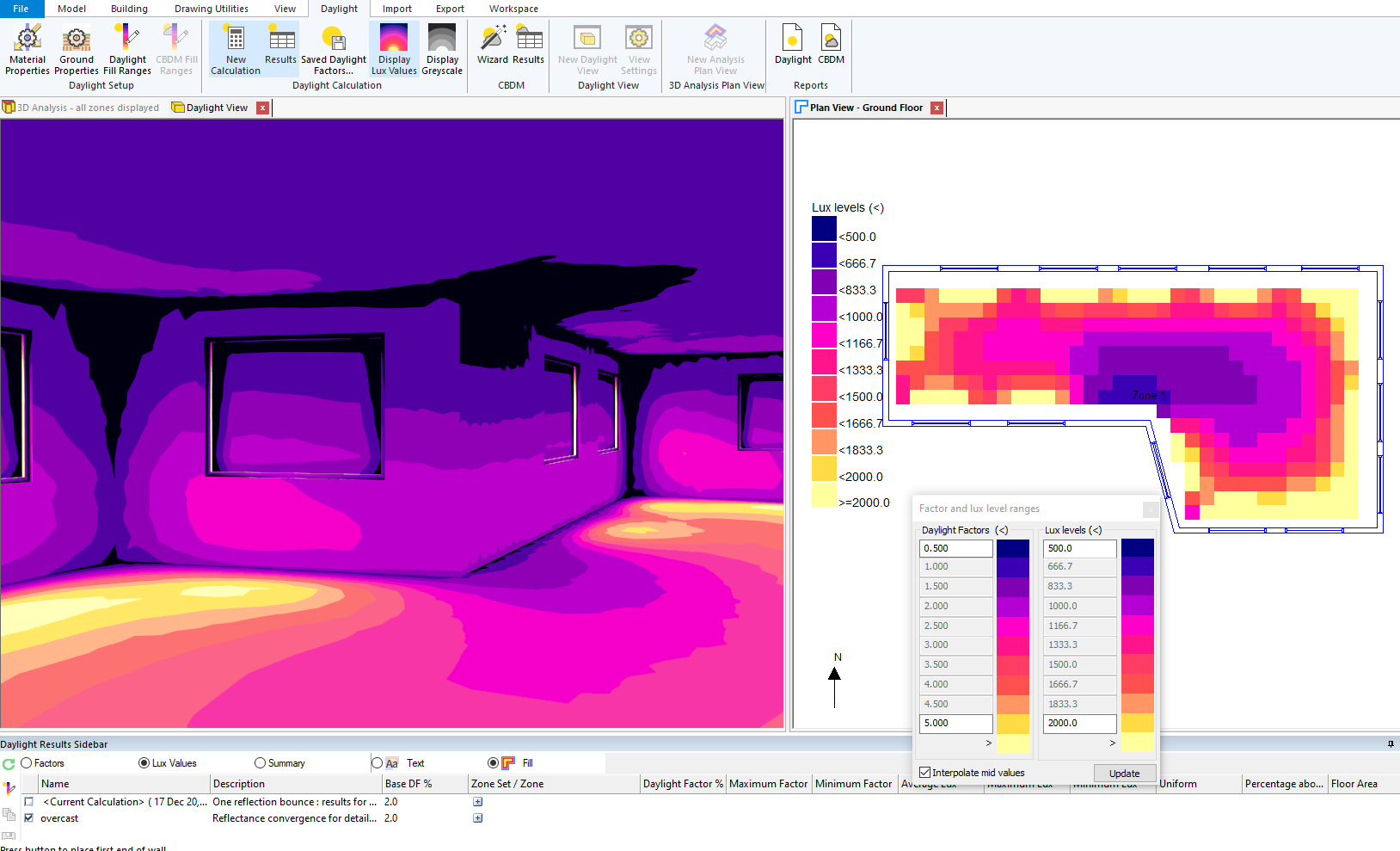
Display Calculation Lux Values
To display the resulting lux values from a recent daylight calculation, go to Daylight >> Daylight Calculation >> Display Lux Values in the ribbon:
Note that the Daylight View Settings dialog is not relevant in this mode and will be closed.
The Daylight Fill ranges dialog defines the colours and lux ranges. These are the same as used in Fill in a plan view and can be changed.
Again the view can be manipulated and the image regenerated. Note that the interactive view does not show the lux value colouring.
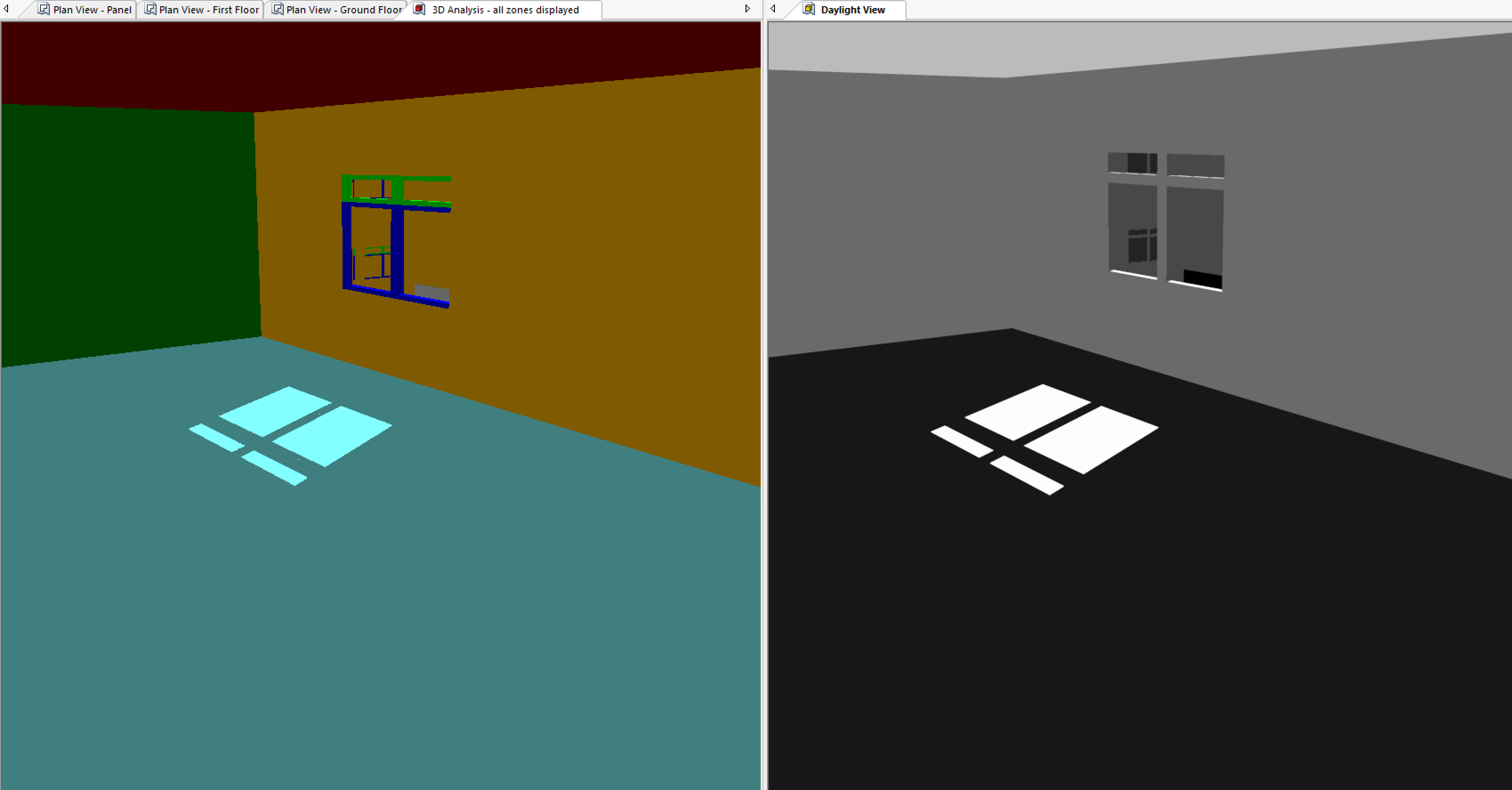
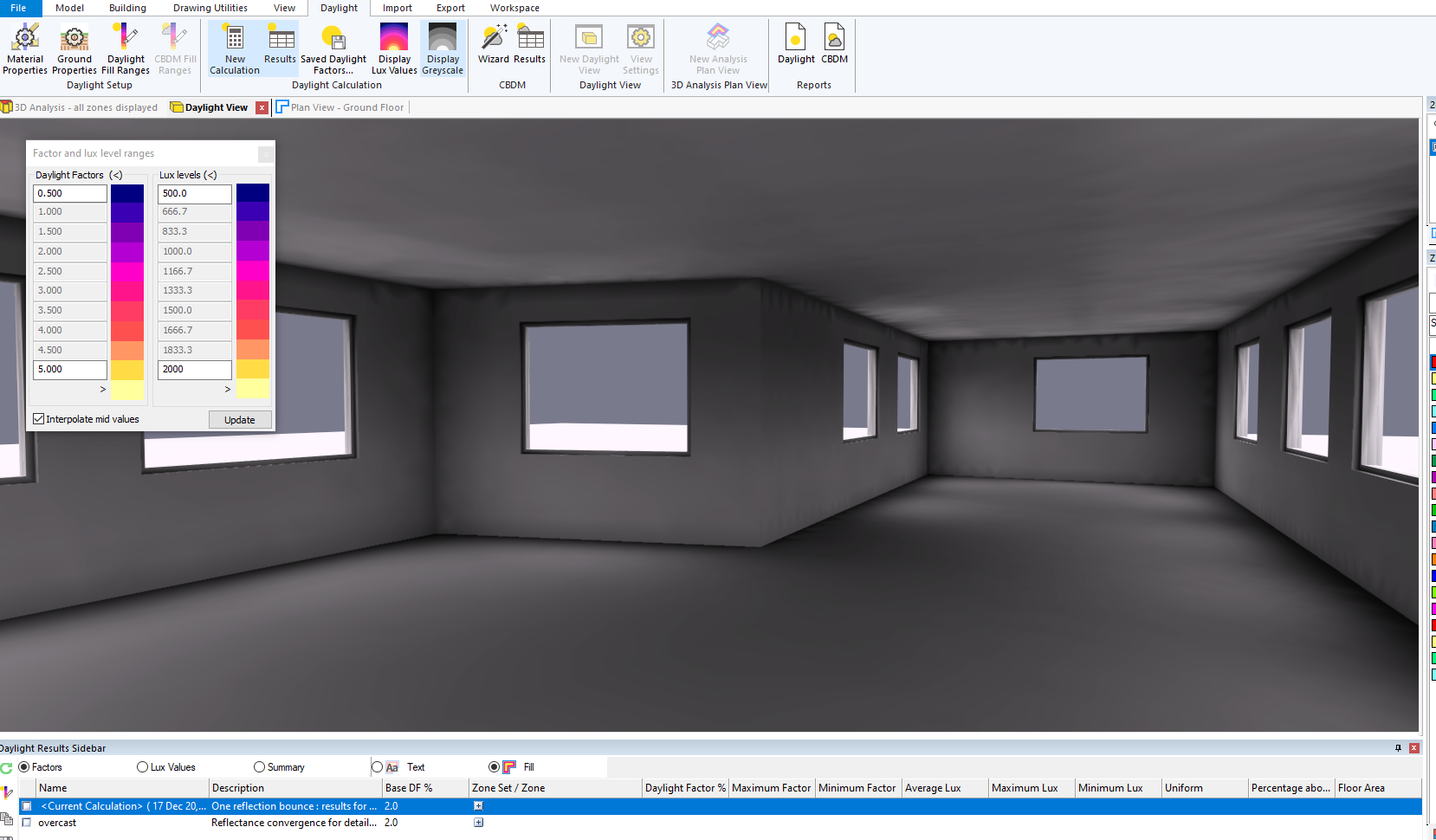
The option Display Greyscale uses the same reflected light solution from the calculation:
The greyscale view of a calculation using a clear sky will show jagged shadow outlines:
In this case the view is showing the light on the calculation mesh generated by the recent daylight calculation. When using the Daylight View Settings dialog to generate a view, the direct light from the sun and sky is calculated by ray tracing and combined with the reflected light solution to get the better image.
Advanced Daylight Calculations
The 3D modeller can also perform more complex daylight calculations that involve one or more basic daylight calculations. Examples include:
Climate Based Daylight Modelling
Right of light (Equivalent First Zone) calculations
BRE 209 calculations
Climate Based Daylight Modelling
Climate Based Daylight Modelling can be performed in the 3D modeller by clicking Analyse >> Daylight >> CBDM in the ribbon.
Unlike the basic daylight calculations, CBDM calculations involve predicting the illuminance within a space throughout the year rather than on one particular day. CBDM calculations also take into consideration the local weather via a Tas Weather File.
Before performing CBDM calculations in the 3D modeller, you should setup the material properties as described in Material Properties.
For more details about CBDM calculations in Tas, including how to view results in the 3D modeller, see the CBDM user guide: https://docs.edsl.net/cbdm/
Right of light & BRE 209
To perform Equivalent First Zone, Permanant Overshadowing, Daylight Distribution, Vertical Sky Component and Annual Probable Sunlight Hours calculations, you should use the Tas3D Daylight Analysis Wizard which is available in the Tas Manager.
This tool is designed to assess the impact of a proposed change to surrounding buildings on existing buildings, so two 3D modeller files are required; an existing model, and a proposed model.
Please see the corresponding user guide for more information.