Inputting Information about the Heating Circuit
You are able to model multiple heating circuits each using a different boiler. Multiple boilers can be modelled per circuit. Select whether they will run in serial, parallel, or staged. Staged boilers will be explained in more detail in the next topic. The boiler or boilers will provide the energy for both space heating and hot water services. CAV and VAV air-side systems can optionally have the AHU heating coil on a different circuit to the heating coil within the zone.
You will be able to set up a basic heating circuit and choose whether or not a tank should be included. You can model a basic heating circuit with a single tank for DHW and solar thermal, or specify whether they each will have their own tank. When two tanks are modelled the boiler will supply the primary tank and the solar thermal will supply the secondary tank.
You can also model combined heat and power, as well as tri-generation CHP with cooling via an absorption chiller powered by the heat output of the CHP.
To model CHP you will need to specify a profile for the back-up boiler. You will need to input a fuel source and part-load (or seasonal) efficiencies. The back-up boiler will provide space heating and will only operate when the CHP is running at full capacity. It can be modelled as a heat pump. You may specify more than one back-up boiler in the editor. Multiple back-up boilers can be modelled in series, parallel, or staged. Each back-up boiler can be assigned a separate fuel source and partload efficiencies.
To specify a CHP system, you will need to enter the combined efficiency, also known as the “total system efficiency” in the literature. Part-load efficiencies can be used. Total system efficiency is the sum of the net useful power and thermal outputs divided by the total fuel input. The fuel input will need to account for distribution losses, i.e., if a distribution efficiency of 90% is entered then the energy input to the system to meet the demand must be sufficient to overcome the stated distribution loss. To achieve this the energy input will be increased by a factor of (1/0.9).
You will also enter the heat-to-power ratio of the CHP. For example, a CHP producing 9MW of usable heat with a heat-to-power ratio of 1.8:1 will be able to output 5MW of electricity. The electricity produced by the CHP will be known as “grid displaced electricity”.
The size fraction for the CHP is needed in order to be able to size it. The size fraction can be a value greater than 1. The size fraction is the proportion of the peak demand which will be met by the CHP.
If the CHP is to be sized on the space heating demand then the size fraction will be the proportion of the peak space heating demand met by the CHP. Note it is not sized on the annual demand. The peak value will be read from the results of the heating design day that the studio will set up for you.
If the CHP is to be sized on the DHW load then the size fraction will be the proportion of the “peak” DHW load met by the CHP.
If the CHP is to be sized on a combination of space heating and DHW demand then the size fraction will be the proportion of the peak of the sum of the space heating and DHW demands met by the CHP.
You can set the priority value to either DHW or heating. For example, if you size the CHP on DHW and you input a size fraction of 1 then the CHP will meet all of the DHW demand provided the priority is set to DHW.
It is generally accepted that a CHP should always be running in order to derive a benefit. Therefore, sizing the CHP and setting the priority to DHW will guarantee this.
The base load in practice might not always be the DHW usage but typically this is the case.
The distribution efficiency on this page does not factor for distribution losses incurred due to DHW usage. These losses will be specified on the Domestic Hot Water Circuit Configuration screen.
Exercise and Notes
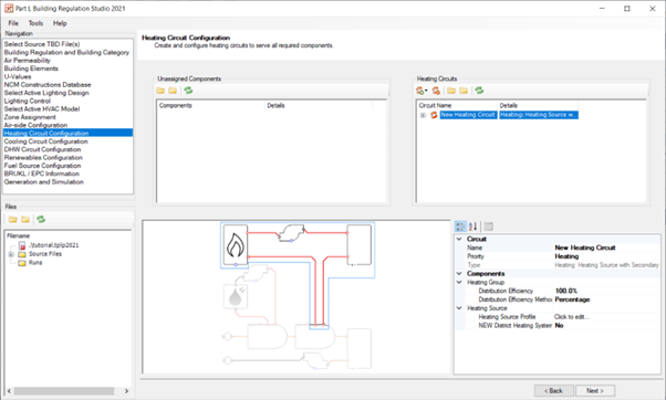
Click on the Add Heating Circuit button on the toolbar and select a heating circuit with primary and secondary tanks.
Alternatively you can create a basic heating circuit in the first instance and then set the type after the fact. You can do this in one of two ways:
Right-click on the basic heating circuit and then point to Set As on the pop-up menu. You will now be able to choose the option that includes a primary tank for the DHW and a secondary tank for the solar thermal.
Drag unassigned components to the right of the screen before having created a heating circuit. A basic heating circuit will automatically be created. You can then edit its type on the right-click menu.
Assuming you’ve added a circuit as per Step 1 drag the unassigned components (zones) that are on the left onto the new heating circuit. You can add all zones in one go by collapsing the folders on the left and then holding down the Shift key to highlight the whole tree view. Just click on the Collapse button on the toolbar if everything’s expanded.
Set the distribution efficiency of the heating group to 90% to increase the energy consumption needed to meet the demand of the heating group by a factor of 1/0.9.