Setting Up a Fancoil System
The bypass factor determines the proportion of air that will pass through the cooling coil and therefore how much air will bypass it altogether. It is commonly used to express the efficiency of a cooling coil. If the contact factor is known then the bypass factor can be calculated using the following relationship: Bypass Factor = 1 - Contact Factor.
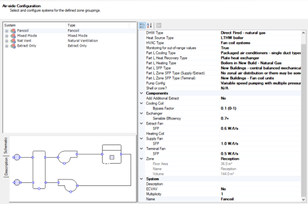
Monitoring for out-of-range values set to True will reduce the heating, cooling, auxiliary, and HWS consumption by 5%.
Exercise and Notes
In this example 90% of the air will come into contact with the cooling coil. You should set the bypass factor to 0.1.
The terminal fan SFP has been specified as 0.3 W per l/s.
The extract fan has been modelled with an SFP of 0.6 W per l/s and the fresh air fan will produce 1.2 W per l/s. This is equivalent to the notional building which will have an SFP in the central AHU of 1.8 W per l/s.
The associated zones will benefit from demand control ventilation as a function of occupancy density where air flow will be regulated by fan speed as opposed to dampers. The auxiliary energy will be adjusted accordingly because flow will be regulated by fan speed. If we had selected dampers instead of fan speed then the auxiliary energy would not be affected by the demand control ventilation option.
Monitoring for out-of-range values = True.