Defining the Lighting Control Strategy
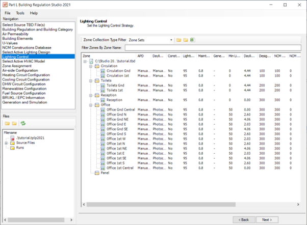
Automatic presence detection
Select a PIR sensor from the drop-down list (click on the down-arrow). The lighting gain will be multiplied by the appropriate factor as per the SBEM Technical Manual.
Options (factors): auto on-dimmed (0.95), auto on-auto off (0.9), manual on-dimmed (0.9), and manual on-auto off (0.82).
Daylight control
Options include a) no daylight control, b) manual daylight control, c) photocell on-off, and d) photocell control dimming. The lighting gain in the actual building will be defined by the appropriate lighting function. If this value is set to photocell on-off then the lighting function that is called will be photocell control. Lighting functions are described in the Building Simulator manual. Specifically, the minimum illuminance level will be set to the target room illuminance defined by the NCM activity. The lighting gain will be at its maximum value (all lights are on) when the illuminance level in the zone is equal to the target room illuminance. Below this illuminance level all lights will be off and the lighting gain will be zero.
Constant illuminance control
Defined in “BS EN 15193:2007 - Energy performance of buildings - Energy requirements for lighting”. This option will trim the lighting power density by 10% in the actual building.
Lamp type
Lighting has been chosen but a full illuminance calculation has not been carried out. If you do not know the efficacy of the lighting system then you can select a lamp type. You can choose a lamp type for each zone to set the efficacy of the lighting system as per Table 12 of the NCM modelling guide (2021) for lamp inference data. Top-lit activities will be given luminaire lumens per circuit watt values which are different from side-lit and unlit activities. Zones in the notional building will be given an efficacy of 95 luminaire lumens per circuit-watt.
Lighting efficacy
The luminaire lumens per circuit-watt of the lighting system. A power density for the general lighting will be inferred and reported in the BRUKL document. Equation 8 in the NCM modelling guide (2021) will be used to pro-rata the luminaire lumens per circuit-watt against the lighting curve for the notional building based on 60 luminaire lumens per circuitwatt. You will need to input a maintenance factor (see below) to satisfy the equation.
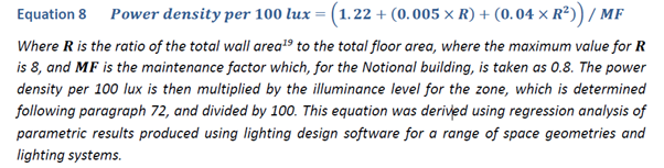
The power density per 100 lux is then multiplied by the illuminance level for the activity type, determined by the NCM database, and divided by 100. Factor for the zone area to give the general lighting in Watts. This value will be output to the BRUKL document.
General lighting power density
A full illuminance calculation has been carried out. Enter the general power density in W/m2 to achieve the design illuminance in each zone. You will also input a design illuminance on this page (see below).
BRE daylight factors
The average diffuse illuminance on the working plane as a percentage of the diffuse illuminance on a horizontal plane outside the building will be calculated. The approach will be based on a simplified BRE method.
Daylight factors from the source TBD
If your source TBD already has daylight factors then these values will be read into the studio and used instead of BRE daylight factors.
Minimum percentage gain
Percentage of the maximum lighting gain which will be used when the natural room illuminance exceeds the target room illuminance as defined by the NCM activity.
Back space sensor
Available for photocell control on-off or dimming. Sets the minimum percentage gain to zero so all lights dim (or switch off) as a function of daylight entering the space. If there is no back space sensor then the minimum percentage gain will be 50% and the daylight factor will be multiplied by a factor of 1.75. Lights in the back half of the zone will always be on but those closer to the window will dim (or switch off) as occupants are introduced to more natural daylight.
Maintenance factor
Defined in the SLL Lighting Handbook as the ratio of maintained illuminance to initial illuminance, where maintained illuminance is the average illuminance over the reference surface at the time maintenance is carried out. It can be thought of as the minimum illuminance that the lighting installation will produce on that surface during its life. Refer to Tables 21.4 to 21.6 for typical values of luminaires, cleaning intervals, and environments. The maintenance factor for the notional building is taken as 0.8 corresponding to a clean space maintained every 3 years assumed in all areas.
Design room illuminance
The illuminance level in lux for which the lighting design was carried out. Where the design illuminance is less than the lighting level defined by the NCM activity the general power density will be automatically pro-rated to the NCM activity lighting level.
NCM Activity room illuminance
The target illuminance in lux. It is the level of natural daylight in the space at which the lighting gain will be at a minimum. This value is set by the BRE database managers and should never be changed by the user.
Parasitic power
The power required by the photocell sensor. It will be added to the total lighting gain. For digitally addressable systems 0.57W/m2 is typical, stand-alone sensors 0.3W/m2 is typical (SBEM Technical Manual).
Photocell sensor on timer clock
Turns the photocell sensor on and off according to the occupancy schedule.
Area cut-off
Maximum lighting gain will be modelled during scheduled hours for zones larger than this value (manual daylight control only).
Display lighting efficacy
The efficacy of the lighting system in lamp lumens per circuit-watt. Applies only to certain NCM activities, e.g., office reception areas.
Automatic time switching
Reduces the annual display lighting energy by 20% in the actual building by modelling automatic time-switching control at zone level.
Exercise and Notes
In this example the default lighting settings will be edited for all office zones. This can be done in one go by selecting all office zones at once before editing the lighting details.
Click on B1_Office 1, hold down the Shift key, and then click on B1_Office 15 to highlight all office zones.
Set the daylight control option to photocell dimming with continuous illuminance control to reduce the power density by 10%.
Input an efficacy of 65 luminaire lumens per circuit-watt.
Daylight factors will be calculated based on the simplified BRE method.
For this example we will model a maintenance factor of 0.8 corresponding to a clean space maintained every 3 years assumed in all areas.
The design room illuminance will be the same as the NCM target.
The photocell sensor will be operating only during the scheduled period.
Apply these changes before moving to the next screen in the studio.