Input Data & Assumptions
The following input data and assumptions were used in this tutorial. You do not have to use these data to follow this tutorial. You can use your own source files and input data. You can also model your own air-side systems and plant information if you wish.
Internal Conditions
The NCM Activities database version 6.1.b will be used for all zones, including offices, circulation, reception, and toilets.
Office zones will have photocell control dimming with constant illuminance control and back space sensors. A full illuminance calculation has not been carried out so we will enter an efficacy for the lights. An efficacy of 65 luminaire lumens per circuit-watt will be specified in these areas. The notional building will be modelled with an efficacy of 95 luminaire lumens per circuit-watt.
Circulation spaces have no daylight control and will be modelled with an efficacy of 55 luminaire lumens per circuit-watt. Reception and toilet areas will have manual daylight control and 55 luminaire lumens per circuit-watt. The notional building will use 95 luminaire lumens per circuit-watt in these areas.
Daylight factor calculations will be based on the simplified BRE method in all spaces because we haven’t done an independent lighting study. A surface will need to be transparent and either exposed or a link to an external zone for a daylight factor to be calculated in this way. The accuracy of this study would be improved by carrying out a more sophisticated lighting analysis. The calculated daylight factor will ignore any external shades.
An air permeability of 3 m3/m2.h at 50Pa will be modelled in all spaces. Infiltration rates will be determined per Tables 4.13 to 4.20 of CIBSE Guide A (2006), using method (b) of paragraph 163 in the NCM modelling guide (2021).
Constructions
Ground Floor: U-value = 0.22 W per m2.K
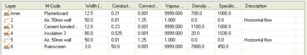
External Wall: U-value = 0.26 W per m2.K
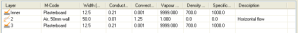
Internal Wall: U-value = 1.778 W per m2.K
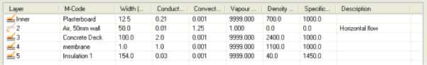
Roof: U-value = 0.18 W per m2.K
Panel: Solar Absorptance = 0.9

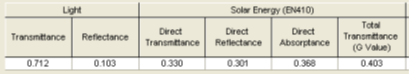
Glazing: U-value = 1.744 W per m2.K
Window Frame: U-value = 2.202 W per m2.K

Mechanical Services
Ventilation in the building will be a mixture of fancoil, mixed mode, natural ventilation, and extract only.
Areas with supply and extract fans will be modelled with a combined SFP of 1.8 W per l/s and 70% heat recovery.
A terminal fan SFP of 0.3 W per l/s will be modelled for the fancoil and mixed mode zones.
Extract only areas to be modelled with a fan SFP of 0.4 W per l/s and a design flow rate of 2 l/s/m2.
Zones with supply and extract ventilation will benefit from demand control ventilation as a function of occupancy density where air flow will be regulated by fan speed. This will serve to reduce the overall auxiliary load.
Areas of the building will be naturally ventilated via openable windows as a function of zone temperature.
Zones that are marked as naturally ventilated or mixed mode will have aperture functions added to the source TBD.
Heating will be provided by a single gas boiler with the following gross part-load efficiencies:
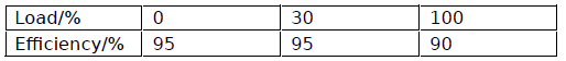
A distribution efficiency of 90% will be modelled for the heating group.
The domestic hot water load will be calculated based on the loads specified in the NCM activities. A total distribution efficiency of 95% (96% distribution efficiency x 99% to account for standing losses) will be modelled for the DHW group.
Mechanically cooled areas will have their cooling demand met by chillers with an SEER of 4.5 and a distribution efficiency of 80%.
All pumps are variable speed with multiple pressure sensors.
Building Management Systems
Light metering with warnings about out-of-range values will be modelled. This will reduce the lighting consumption by 5%, and therefore the CO2 emissions will also be reduced. The building will have automatic monitoring and targeting with alarms for out-of-range values. This will reduce the heating, cooling, auxiliary, and DHW consumption by 5%, and therefore the CO2 emissions will also be reduced.
Electricity power factor correction will be set to >0.95. Anything that uses grid supplied electricity as a power source will have its CO2 emissions adjusted by 2.5%. This adjustment will be made after the 5% has been taken off the consumption due to management factors. In this example the adjustment will be made to the chiller, lighting, fans, and pumps to further reduce their CO2 emissions.
Shading
External shading will be applied to the south facing facade and will begin at floor level. Solar absorptance will be 53%.
The shading device will have 8 equally spaced horizontal fins each with a depth of 0.3m. The height of the shade will be 3 metres, which is the same as the floor height.
Renewables
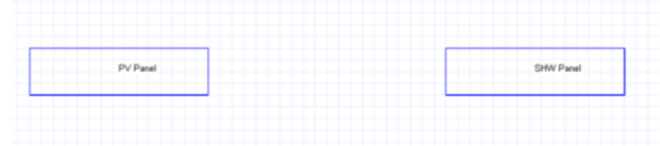
The building will have approximately 60m2 of photovoltaic panels and the same of solar hot water for on-site electricity generation and solar thermal heating for HWS. The panels will be added to the geometry to allow for the effect of shading to be modelled but there is a facility to model these energy sources without surfaces.
PV panel efficiency will be 20% at all irradiance points as this was the only information available at the time.
The SHW maximum panel efficiency will be set to 76%, and a design flow rate of 0.02l/s (typical) will be modelled.
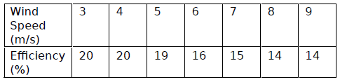
A wind turbine will be added to the model and a multiplication factor of 3 will be used. The amount of energy that is generated by having wind turbines providing power for the building will be calculated. The efficiency will be input as a function of wind speed:
Natural & Mixed Mode Ventilation
For naturally ventilated areas (circulation zones) the windows will start to open when the zone dry-bulb temperature reaches 21 degrees C. The heating set-point in these zones is 20 degrees C (as per the NCM database) so the heating will be off when the windows begin to open. They will be open at their maximum proportion (90%) when the temperature in the zone is 22 degrees C. When the outside temperature exceeds the inside temperature the windows will begin to close. The windows will be fully closed when the outside temperature is 1 degree C above the zone temperature.
For mixed mode areas (office zones) the windows will start to open when the zone dry-bulb temperature reaches 23 degrees C. The heating set-point in these zones is 22 degrees C so the heating will be off when the windows begin to open. The apertures will be fully open (90% opening proportion) at 24 degrees C. When the temperature in the zone is 25 degrees C the apertures will begin to close and at 26 degrees C will be fully closed to allow for mechanical cooling to be turned on.
The office zones will be mechanically cooled to 27 degrees C so there is no risk that the windows will be open when the zones are being cooled by mechanical means.
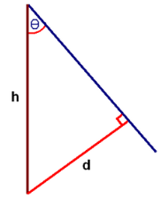
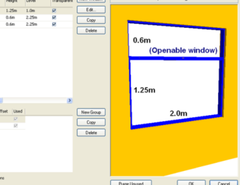
The openable area of the window group will be modelled with a height of 0.6m and a width of 2.0m (see image below) and will be top-hung. The proportion by which the window is said to be open is determined by dividing the throat size (d) by the height of the window (h), where the ratio d/h is 1 when theta is 90 degrees because sin(90)=1. You can see from the cross-section below that the throat size, d can be expressed as h.sin(theta). The approximate angle in degrees by which the window can be opened is 64 at which point the openable proportion will be 0.9 because sin(64) is about 0.9, save for rounding.
Screenshot of the Windows dialog in the 3D Modeller
Cross-section to show window height (h), throat size (d), and openable angle (theta)